Battery cell health monitoring using eddy current sensing

a battery cell and eddy current technology, applied in secondary cells, battery servicing/maintenance, instruments, etc., can solve the problems of reducing the value of the approach, unable to accurately measure the deflection of the battery in-situ, and incurring error on the overall measurement, etc., to achieve the effect of cost reduction, high cost of the interrogation system, and high accuracy

Inactive Publication Date: 2015-11-26
AMPHENOL THERMOMETRICS
View PDF0 Cites 16 Cited by
  • Summary
  • Abstract
  • Description
  • Claims
  • Application Information

AI Technical Summary

Benefits of technology

[0009]In one embodiment, the sensing system comprises: a battery module comprising a plurality of battery cells; an eddy current sensor coil placed adjacent to one or more of the plurality of cells to determine cell expansion during cell operation; and a batt

Problems solved by technology

However, there has lacked an accurate method to make in-situ measurements of the deflection of the battery when the cell is packaged as part of a pack that would be suitable for field installation either in grid storage or on-road, vehicle applications.
However, they suffer from several drawbacks.
First, they provide an indirect measurement of the deflection of the cell and require the battery system to utilize addition

Method used


Image

  • Battery cell health monitoring using eddy current sensing
  • Battery cell health monitoring using eddy current sensing
  • Battery cell health monitoring using eddy current sensing

Examples


first embodiment

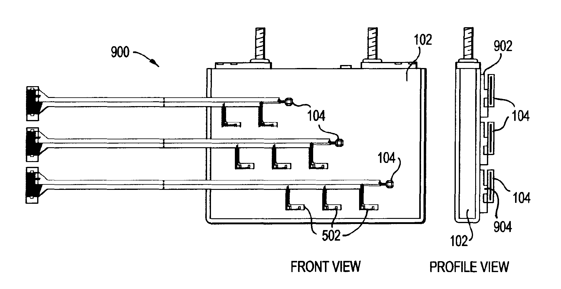
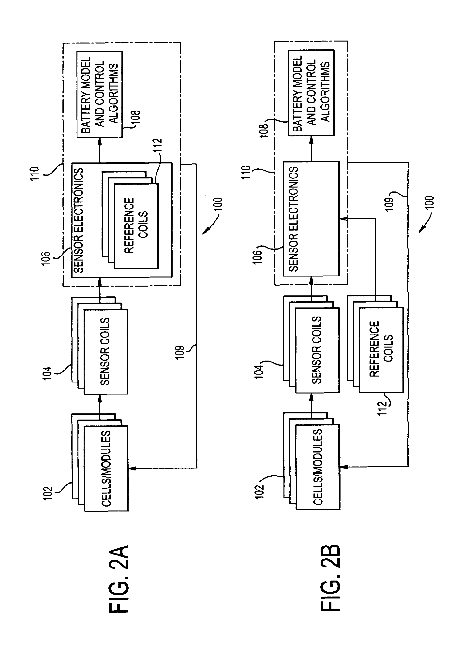
[0037]A first embodiment is illustrated in FIGS. 2A and 3A, where the sensor electronics 106 may include at least one reference coil 112. Reference coil(s) 112 are typically identical to the sensor coil 104 in either manufacturing or nominal value of inductance and resistance and are used as a baseline to measure the change in sensed gap between the battery cells 102. Specifically, the reference coil 112 provides a reference voltage which accounts for common mode noise in the system. In operation, the reference coil 112 accounts for common mode noise, where environmental changes that would affect both the sensor coil 104 and the reference coil 112, such as a temperature change, would not cause a change in the difference of the signals. As such, the reference coil 112 remains at a fixed position that does not move, while the sensor coil 104 is affected by displacement of the battery cell 102. In one embodiment as discussed herein, the sensor coil 104 is positioned on the wall of the ...

second embodiment

[0038]A second embodiment is illustrated in FIGS. 2B and 3B, where the reference coil(s) 112 may be located outside of the sensor electronics 106 and in proximity to the sensor coil(s) 104 so that it experiences the same environmental changes as the sensor coil(s) 104. In this second configuration 320, as illustrated in FIG. 3B, the reference coil 112 is disposed on or near a cell 102 in an area where the wall of the cell 102 is not moving relative to the reference coil 112 during charge or discharge, and thus not modulating the reference coil 112. For instance, the reference coil 112 can be built on the same substrate as sensor coil(s) 104, but spaced apart from sensor coil(s) 104. The reference coil 112 can be placed adjacent to the sensor coil(s) 104, though the distance to the battery cell 102 must be held constant so as to not be affected by displacement changes of cell 102, which would negate the changes sensed by the sensor coil 104. One method of doing so is to mount the ref...


PUM


Abstract

The invention provides a battery sensing system comprising a battery module comprising a plurality of battery cells, at least one sensor coil coupled to or placed adjacent to one of more of the plurality of battery cells to determine cell expansion during cell operation, and a battery management system comprising one or more processors and/or microcontrollers that control operation of the plurality of battery cells.

Description

RELATED APPLICATIONS[0001]This application is a continuation-in-part of International Patent Application No. PCT / US15 / 12707 filed Jan. 23, 2015 which claims priority to U.S. Provisional Application No. 61 / 969,430 filed Mar. 24, 2014, the contents of which are hereby incorporated by reference.STATEMENT REGARDING FEDERALLY SPONSORED RESEARCH & DEVELOPMENT[0002]This invention was made with Government support under contract number DE-AR0000269 awarded by the Department of Energy. The Government has certain rights in the invention.BACKGROUND[0003]Embodiments of the present disclosure relate generally to a method and system for monitoring battery cell health. More specifically, the present disclosure relates to a method and system for monitoring battery cell health using eddy current sensing.[0004]There is an increasing prevalence to provide electrochemical storage devices such as batteries and capacitors in portable power generation from cell phones and laptops to portable power generati...

Claims


Application Information

Patent Timeline
IPC IPC(8): H01M10/48G01R31/36H01M50/569
CPCH01M10/482H01M2010/4271G01R31/3651G01R31/3658G01B7/16H01M10/052H01M10/425H01M10/4257H01M10/48H01M2220/20Y02E60/10H01M50/569G01R31/367G01R31/396
Inventor KNOBLOCH, AARON J.PLOTNIKOV, YURI ALEXEYEVICHKAPUSTA, CHRISTOPHER JAMESKARP, JASON HARRISLIN, YIZHEN
Owner AMPHENOL THERMOMETRICS
Why Eureka
Try Eureka