Electrical receptacle connector

a technology of electric receptacles and connectors, which is applied in the direction of coupling device details, coupling device connections, electric discharge lamps, etc., can solve the problems of increasing the possibility, various electronic components in the device will suffer from electromagnetic interference (emi) or radio frequency interference (rfi), and the high speed electrical transmission in these devices can produce electromagnetic emissions. , to reduce the spacing, reduce the ground resistance, and improve the securing force

Active Publication Date: 2015-11-26
ADVANCED CONNECTEK INC
View PDF11 Cites 24 Cited by
  • Summary
  • Abstract
  • Description
  • Claims
  • Application Information

AI Technical Summary

Benefits of technology

[0007]In view of the above problems, the instant disclosure provides an electrical receptacle connector comprising an insulated housing, a plurality of upper-row plate terminals, a plurality of lower-row plate terminals, and a metallic shell. The insulated housing comprises a base portion and a tongue portion extending from one side of the base portion. The tongue portion comprises an upper surface and a lower surface. The upper-row plate terminals comprise a plurality of upper-row plate signal terminals, at least one upper-row power terminal, and at least one upper-row plate ground terminal. Each of the upper-row plate terminals is held on the base portion and the tongue portion and at the upper surface. Each of the upper-row plate terminals comprises an upper-row contact segment, an upper-row connecting segment, and an upper-row soldering segment. For each upper-row plate terminal, the upper-row connecting segment is at the base portion and the tongue portion, the upper-row contact segment is extending from one of two ends of the upper-row connecting segment to be at the upper surface, and the upper-row soldering segment is extending from the other end of the upper-row connecting segment to protrude out of the base portion. The lower-row plate terminals comprise a plurality of lower-row plate signal terminals, at least one lower-row power terminal, and at least one lower-row ground terminal. Each of the low-row plate terminals is held on the base portion and the tongue portion and at the lower surface. Each of the lower-row plate terminals comprises a lower-row contact segment, a lower-row connecting segment, and a lower-row soldering segment. For each lower-row plate terminal, the lower-row connecting segment is at the base portion and the tongue portion, the lower-row contact segment is extending from one of two ends of the lower-row connecting segment to be at the lower surface, and the lower-row soldering segment is extending from the other end of the lower-row connecting segment to protrude out of the base portion. The metallic shell defines a receiving cavity therein. The insulated housing is in the metallic shell. The metallic shell comprises a top cover plate, a rear cover plate, and a plurality of pins. The top cover plate is located atop the base portion and the tongue portion. The rear cover plate is extending downwardly to the rear side of the base portion from the rear side of the top cover plate, and the rear cover plate comprises a bottom surface and a bent sheet substantially perpendicular to an outer wall of the rear cover plate and extended outward from the outer wall of the rear cover plate. The pins are extending downwardly from the bottom surface.
[0008]In conclusion, the rear cover plate has a plurality of pins to be soldered on the circuit board for reducing ground resistance and EMI. Moreover, the decrease of the spacing between the bottom surface of the rear cover plate and the circuit board effectively achieves desirable effects of EMI and RFI reductions. In addition, the pins improve the securing force between the electrical receptacle connector and the circuit board, so that the electrical receptacle connector would have desirable bending test results and wrenching strength. Besides, since the upper-row plate terminals and the lower-row plate terminals are arranged upside down, and the pin configuration of the upper-row plate signal terminals is left-right reversal with respect to that of the lower-row plate signal terminals. Accordingly, when the electrical plug connector is inserted into the electrical receptacle connector by a first orientation where the upper plane of the electrical plug connector is facing up, the upper-row elastic terminals of the electrical plug connector are in contact with the upper-row plate signal terminals of the electrical receptacle connector. Conversely, when the electrical plug connector is inserted into the electrical receptacle connector by a second orientation where the lower plane of the electrical plug connector is facing up, the upper-row elastic terminals of the electrical plug connector are in contact with the lower-row plate signal terminals of the electrical receptacle connector. Consequently, the inserting orientation of the electrical plug connector is not limited when inserting into the electrical receptacle connector.
[0009]Detailed description of the characteristics and the advantages of the instant disclosure is shown in the following embodiments, the technical content and the implementation of the instant disclosure should be readily apparent to any person skilled in the art from the detailed description, and the purposes and the advantages of the instant disclosure should be readily understood by any person skilled in the art with reference to content, claims and drawings in the disclosure.

Problems solved by technology

This increases the possibility that the various electronic components in the device will suffer from electromagnetic interference (EMI) or radio frequency interference (RFI) either from RF components such as the antenna, microphone components, RF power amplifiers, etc and subsystems in the device and / or from external sources.
The high speed electrical transmission in these devices can produce electromagnetic emissions, which may leak from the connection between the plug connector and its mating connector.
These emissions can cause problems in high speed signal transmissions in that they can negatively influence wireless communication between two devices.
The transmission rate of USB 2.0 is insufficient.
From the test results on the distribution of electromagnetic emission leakage, it can be known that a significant magnitude of electromagnetic emissions would leak from the gap, resulting in EMI and RFI problems during signal transmission.
Moreover, regarding the rear cover plate A11 be devoid of pins, the securing force between the electrical receptacle connector and the circuit board would be insufficient.

Method used


Image

  • Electrical receptacle connector
  • Electrical receptacle connector
  • Electrical receptacle connector

Examples


Embodiment Construction

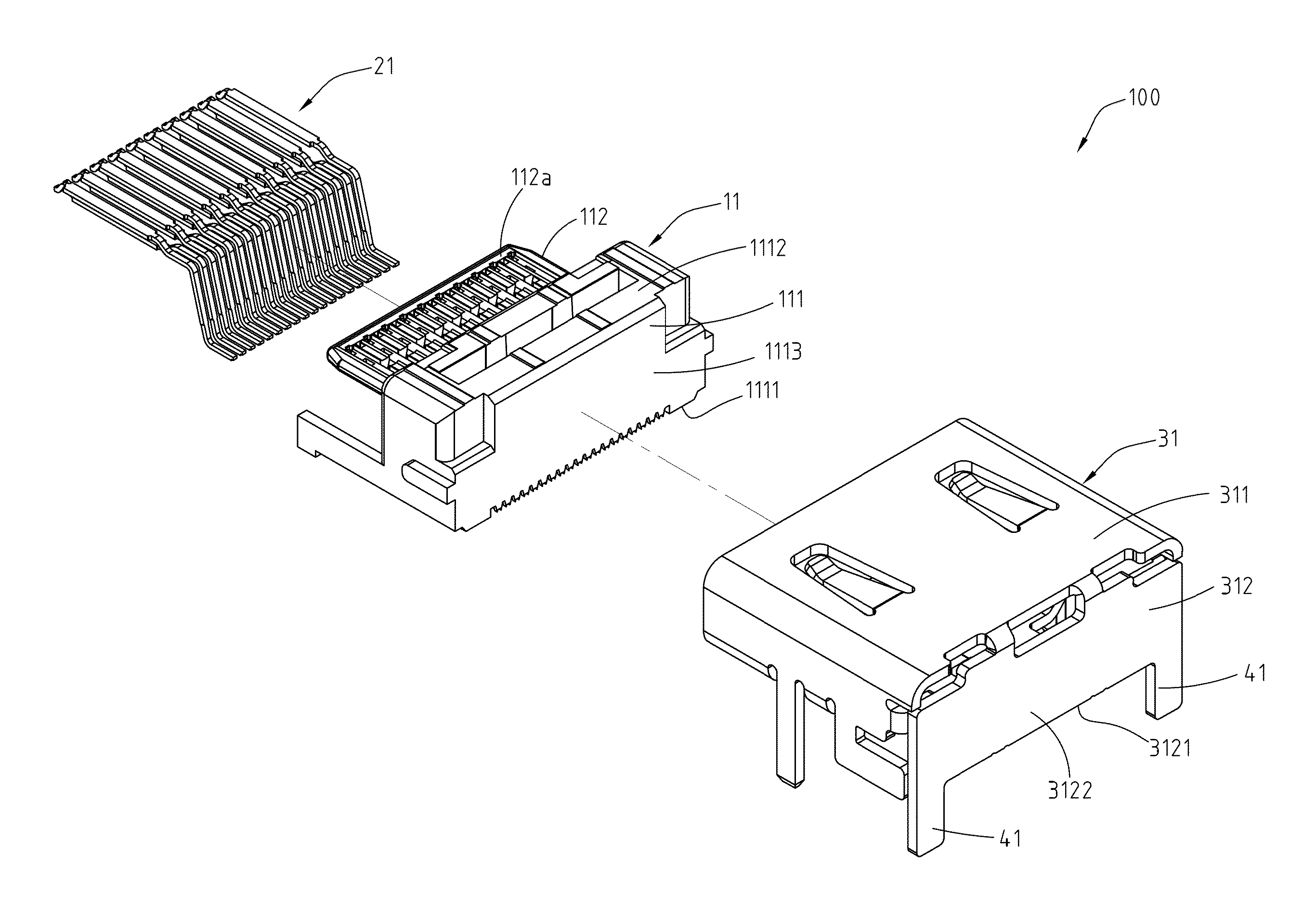
[0026]Please refer to FIG. 3, FIG. 4, and FIG. 5, illustrating an exemplary embodiment of an electrical receptacle connector 100 according to the instant disclosure. FIG. 3 illustrates a perspective view of the electrical receptacle connector 100. FIG. 4 illustrates an exploded view of the electrical receptacle connector 100. FIG. 5 is a schematic view of EMI analysis for the electrical receptacle connector 100. Here, the electrical receptacle connector 100 may be of a type-C USB connection interface specification (as shown in FIG. 6). In this embodiment, the electrical receptacle connector 100 comprises an insulated housing 11, a plurality of receptacle terminals 21, and a metallic shell 31.

[0027]Please refer to FIG. 4 and FIG. 5, in which the insulated housing 11 is an elongate member, and the insulated housing 11 comprises a base portion 111 and a tongue portion 112. Here, the base portion 111 and the tongue portion 112 are formed by insert-molding technique, and the tongue porti...


PUM


Abstract

An electrical receptacle connector includes an insulated housing, plate terminals, and a metallic shell. The insulated housing includes a base portion. The plate terminals are at the insulated housing. The plate terminals include soldering segments exposed out of the bottom of the base portion. The metallic shell encloses four sides of the insulated housing and includes a top cover plate, a rear cover plate, and pins. The top cover plate is located atop the base portion. The rear cover plate is extending downwardly to the rear side of the base portion from the rear side of the top cover plate. The rear cover plate includes a bottom surface and a bent sheet substantially perpendicular to an outer wall of the rear cover plate and extended outward from the outer wall of the rear cover plate, and the pins are extending downwardly from the bottom surface.

Description

CROSS-REFERENCES TO RELATED APPLICATIONS[0001]This non-provisional application claims priority under 35 U.S.C. §119(a) on patent application Ser. Nos. 10 / 320,8993 and 10 / 4,105,188, filed in Taiwan, R.O.C. on 2014 May 22 and 2015 Feb. 13, the entire contents of which are hereby incorporated by reference.FIELD OF THE INVENTION[0002]The instant disclosure relates to an electrical connector, and more particularly to an electrical receptacle connector.BACKGROUND[0003]Currently, the increase in the functionality of various electronic devices is driving the demand for smaller and smaller devices that are easier and more convenient for users to carry and use. This causes many electrical / electronic components within the device to be located closer together. This increases the possibility that the various electronic components in the device will suffer from electromagnetic interference (EMI) or radio frequency interference (RFI) either from RF components such as the antenna, microphone compon...

Claims


Application Information

Patent Timeline
Patent Type & Authority Applications(United States)
IPC IPC(8): H01R13/516
CPCH01R13/516H01R13/6582H01R13/6594H01R24/62
Inventor KAO, YA-FENTSAI, YU-LUNHOU, PIN-YUANWANG, WEN-YUTSAI, WEN-HSIENCHEN, MAO-SHENG
Owner ADVANCED CONNECTEK INC
Why Eureka
Try Eureka