
Method, Base Station, and Terminal for Notifying and Receiving Downlink Demodulation Pilot Frequency Control Signaling

Inactive Publication Date: 2015-11-26
ZTE CORP
View PDF8 Cites 26 Cited by
  • Summary
  • Abstract
  • Description
  • Claims
  • Application Information

AI Technical Summary

Benefits of technology

The present invention provides a method for improving pilot control signaling to enhance the accuracy of channel estimation and increase system capacity. The method involves standardizing information between the base station and user equipment to indicate the parameters of pilot control signaling, which results in better use of pilot to achieve the effects of orthogonality and interference randomization.

Problems solved by technology

However, since discussions at the later stage take the heterogeneous network into consideration and introduce more scenarios, and also due to the complexity of CoMP technology and the limited time for R10 discussion, it was finally determined that no extra CoMP standardized content would be introduced at the R10 stage, but the needs of CoMP part can be considered when designing the CSI-RS, therefore there has been no further discussion on the CoMP technology after the 60bis conference.

Method used


Image

  • Method, Base Station, and Terminal for Notifying and Receiving Downlink Demodulation Pilot Frequency Control Signaling
  • Method, Base Station, and Terminal for Notifying and Receiving Downlink Demodulation Pilot Frequency Control Signaling

Examples


first embodiment

The First Embodiment

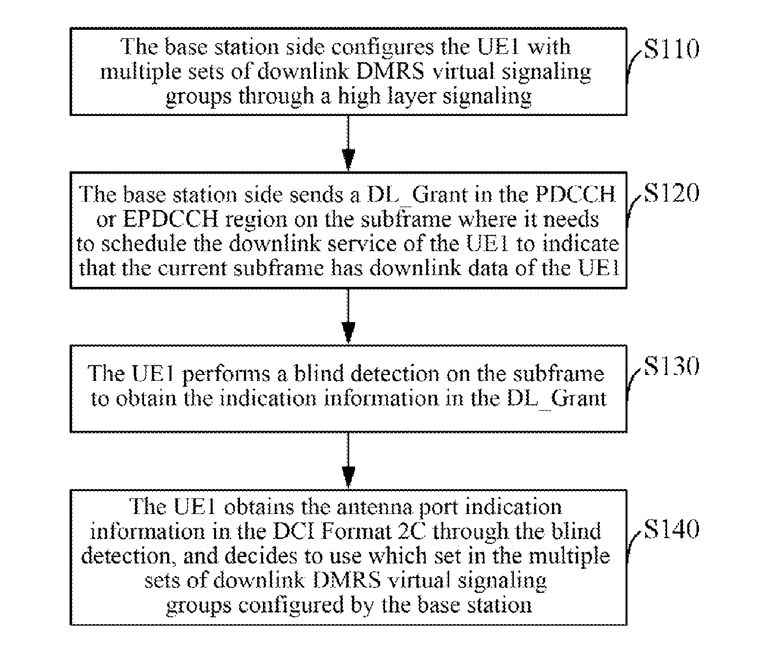
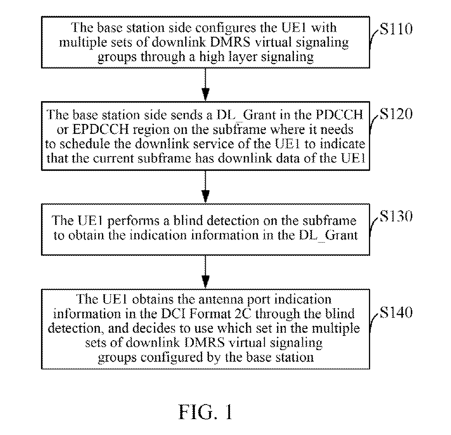
[0150]In the present embodiment, it assumes that UE1 is a user of R11. As shown in FIG. 1, the present embodiment comprises the following steps:

[0151]in step S110, the base station side configures the UE1 with multiple sets of downlink DMRS virtual signaling groups through a high layer signaling.

[0152]In step S120, the base station side sends a downlink grant signaling (DL_Grant) in the PDCCH or EPDCCH region on the subframe where it needs to schedule the downlink service of the UE1 to indicate that the current subframe has downlink data of the UE1.

[0153]In step S130, the UE1 performs a blind detection on the subframe to obtain the indication information in the DL_Grant.

[0154]In step S140, the UE1 obtains the antenna port indication information in the DCI Format 2C through the blind detection, and decides to use which set in the multiple sets of downlink DMRS virtual signaling groups configured by the base station.

[0155]For example:

[0156]when the UE1 obtains that...

second embodiment

The Second Embodiment

[0160]Assuming that UE1 is a user of R11, the base station side configures the UE1 with multiple sets of downlink DMRS virtual signaling groups through a high layer signaling, and then it sends the DL_Grant in the PDCCH or EPDCCH region on the subframe where it needs to schedule the downlink service of the UE1 to indicate that the current subframe has downlink data of the UE1. The UE1 performs a blind detection on the subframe to obtain the indication information in the DL_Grant.

[0161]Then the UE1 obtains new data indication information in the disable TB in the DCI Format 2C through the blind detection, and decides to use which set in the multiple sets of downlink DMRS virtual signaling groups configured by the base station.

[0162]For example:

[0163]when the UE1 obtains that the new data indication information in the disable TB and transmitting in one layer in the DL_Grant is NDI=0 in accordance with the blind detection, the first virtual signaling parameter set o...

third embodiment

The Third Embodiment

[0165]Assuming that the UE1 is a user of R11, the base station side configures the UE1 with multiple sets of downlink DMRS virtual signaling groups through a high layer signaling, and then it sends the DL_Grant in the PDCCH or EPDCCH region on the subframe where it needs to schedule the downlink service of the UE1 to indicate that the current subframe has downlink data of the UE1. The UE1 performs a blind detection on the subframe to obtain the indication information in the DL_Grant.

[0166]Then, the UE1 obtains the new data indication information and antenna port indication information in the disable TB in the DCI Format 2C through the blind detection, and decides to use which set in the multiple sets of downlink DMRS virtual signaling groups configured by the base station.

[0167]For example:

[0168]when the UE1 obtains that the new data indication information in the disable TB and transmitting in one layer in the DL_Grant is NDI=0, and the antenna port in the able T...


PUM


Abstract

A method for notifying a downlink demodulation pilot control signaling, includes: a base station side notifying a user equipment (UE) side of an index of a virtual signaling group and / or index of port offset signaling group used when generating a downlink pilot sequence and / or mapping the generated downlink pilot sequence through at least one of the following information: UE-specific or common high layer signaling; antenna indication information of DL_Grant; new data indication information in a Disable TB signaling in the DL_Grant; scrambling indication information in the DL_Grant; in a UE-specific or common search space, an aggregation level of the DL_Grant, a relative position of a first control channel element of the DL_Grant in the UE-specific or common search space, a subframe number where the DL_Grant is located and a system frame number where the DL_Grant is located.

Description

TECHNICAL FIELD[0001]The present document relates to the field of communications, and more particularly, to a method for notifying and receiving a downlink demodulation pilot control signaling, as well as a base station and a terminal.BACKGROUND OF THE INVENTION[0002]On the basis of the two versions R8 and R9, the version R10 of the Long Term Evolution (LTE) system adds many new features, for example, pilot characteristics such as DMRS (Demodulation Reference Signal) and CSI-RS (Channel State Information Reference Signal), and transmission and feedback characteristics such as eight antenna supporting, especially the eICIC (enhanced Inter-Cell Interference Cancelling) technology, which further considers the inter-cell interference cancelling technology on the basis of considering the R8 / 9 ICIC.[0003]Technologies for solving the problem of inter-cell interference mainly consider avoiding inter-cell interference in a homogeneous network at the early stage of the R10, wherein the mainst...

Claims


Application Information

Patent Timeline
IPC IPC(8): H04W72/12
CPCH04W72/1294H04L5/0051H04L5/0053H04L5/0073H04W72/23H04L1/0038
Inventor GUO, SENBAOSUN, YUNFENGZHANG, JUNFENGCHEN, DONGLIZHANG, WENFENG
Owner ZTE CORP
Learn More