Electronic atomization device with adjustable air inlet

a technology air inlet, which is applied in the direction of inhalators, tobacco, other medical devices, etc., can solve the problems of battery assembly damage and dirty outside surface of electronic atomization device, and reduce the possibility of condensate and liquid flavor, and reduce the possibility of battery assembly damage

Inactive Publication Date: 2015-12-03
SHENZHEN JIESHIBO TECH
View PDF6 Cites 108 Cited by
  • Summary
  • Abstract
  • Description
  • Claims
  • Application Information

AI Technical Summary

Benefits of technology

[0027]As disclosed in the present invention, the electronic atomization device has an air inlet disposed at the upper portion of the atomizer but not at the lower portion thereof, which can reduce the possibility of the condensate and liquid flavor flowing out of the electronic atomization device when the electronic atomization d

Problems solved by technology

Generally, the air inlet is arranged at the bottom of the electronic atomization device and cannot be closed when not in use, thus the condensate and liquid flavor are very easy to flow to the outside surface of the electronic atomizati

Method used


Image

  • Electronic atomization device with adjustable air inlet
  • Electronic atomization device with adjustable air inlet
  • Electronic atomization device with adjustable air inlet

Examples


first embodiment

The First Embodiment

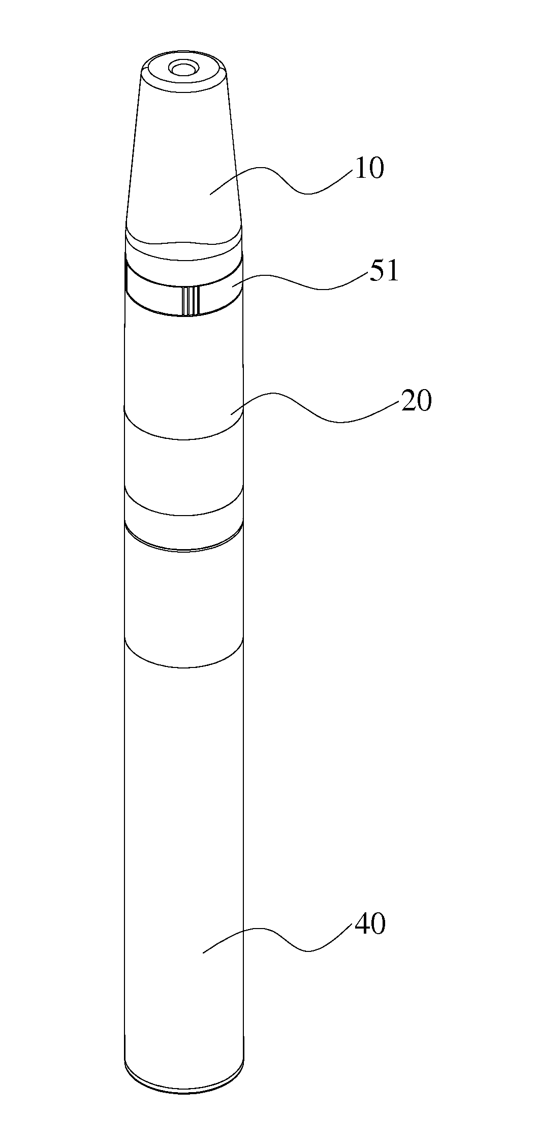
[0049]FIG. 1 to FIG. 8 shows the detailed structures of the electronic atomization device according to the first embodiment of the present invention.

[0050]The electronic atomization device with an adjustable air inlet of the first embodiment includes a cigarette holder 10, an atomizer 20 connected to the cigarette holder 10 and a battery assembly 40 for supplying power to the atomizer 20.

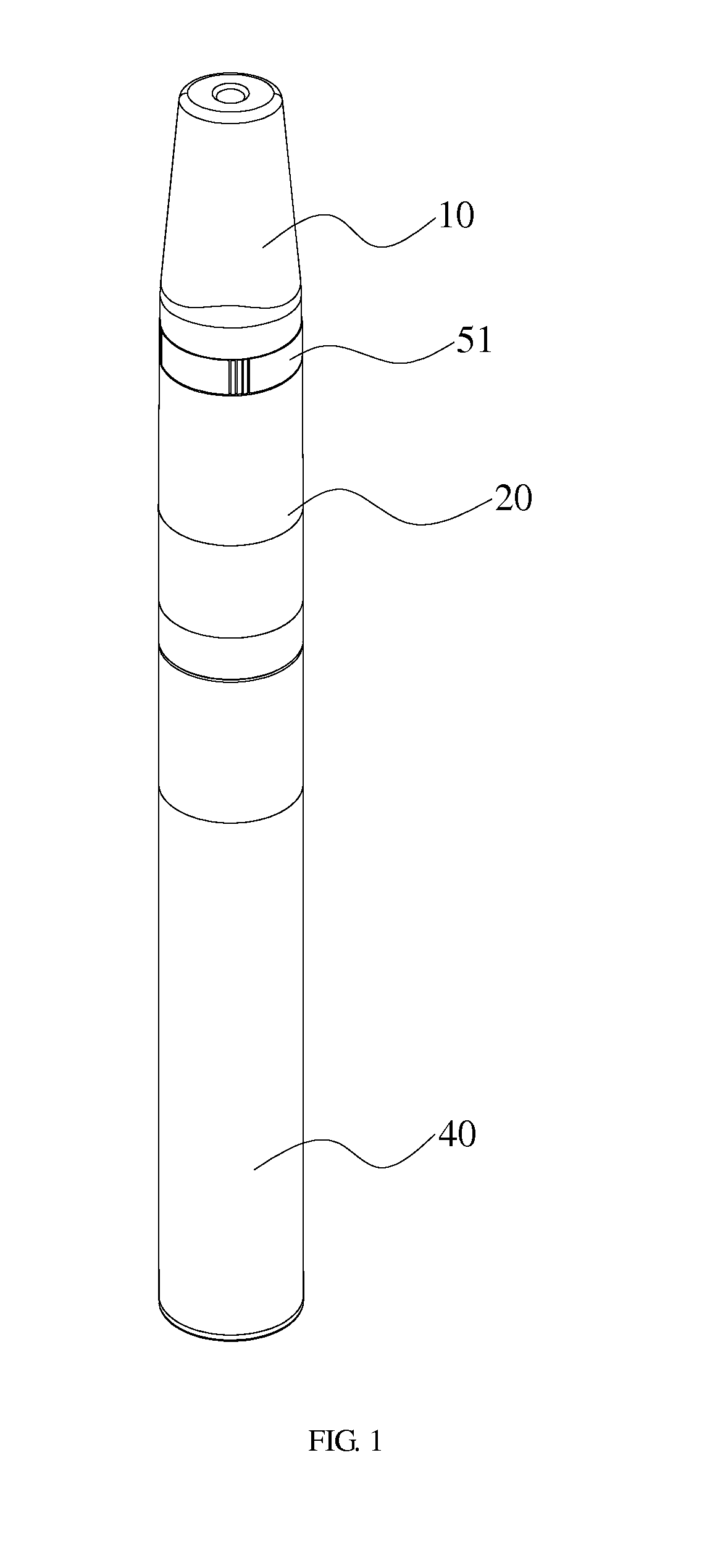
[0051]There are provided an air inlet 21 (shown in FIG. 2 and FIG. 8) with an upward opening and disposed at the upper portion of the atomizer 20 and a switch assembly 50 disposed between the atomizer 20 and the cigarette holder 10 for opening or closing the air inlet 21.

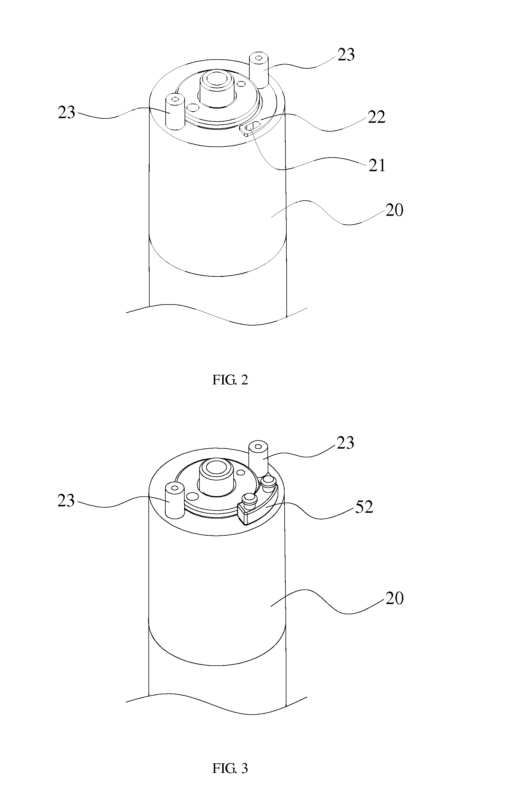
[0052]The switch assembly 50 includes a round ring 51 sandwiched between the atomizer 20 and the cigarette holder 10 and a sealing block 52 fixed in the round ring 51 for opening or closing the air inlet 21. The sealing block 52 closely contacts with the upper surface 22 of the air inlet 21. The round ring 51 is ...

second embodiment

The Second Embodiment

[0057]The differences between the second embodiment and the first embodiment are the structures of the cigarette holder, switch assembly and battery assembly, all of which are shown in FIG. 9 to FIG. 20.

[0058]In the second embodiment, as shown in FIG. 9 to FIG. 12, the cigarette holder 60 includes a smoke channel 61, which is provided within the cigarette holder 60 and connected to the atomizer, and two smoke outlets 62 connected to the smoke channel 61 and disposed at a sidewall of the cigarette holder 60. The smoke outlets are disposed at an upper portion of the cigarette holder 60 uniformly. Specifically, the two smoke outlets 62 are disposed at the upper portion of the cigarette holder 60 symmetrically and the upper portion of the cigarette holder 60 has an elliptical cross section. The two smoke outlets 62 are disposed at two intersections between the long axis of the elliptical section and the outside wall of the cigarette holder 60, respectively. In other...


PUM


Abstract

Disclosed is an electronic atomization device with an adjustable air inlet, which includes a cigarette holder, an atomizer connected to the cigarette holder and a battery assembly for supplying power to the atomizer. An air inlet is disposed at an upper portion of the atomizer for connecting the atomizer to outside world and a switch assembly is disposed between the atomizer and the cigarette holder for opening or closing the air inlet. As disclosed in the present invention, the air inlet can be closed completely by means of the switch assembly thereby preventing the condensate and liquid flavor from flowing to the outside world, avoiding the outsider surface of the electronic atomization device getting dirty and reducing the possibility of the damage of the battery assembly.

Description

FIELD OF THE INVENTION[0001]The present invention relates to electronic atomization device and, in particular, it concerns an electronic atomization device with an adjustable air inlet.BACKGROUND OF THE INVENTION[0002]Electronic atomization device, also called electronic cigarette, atomization tobacco with low temperature, is mainly used for reducing harms brought by smoking traditional cigarette. Its appearance and taste are similar to cigarette and it has more flavors than even normal cigarette does. It can also create a cloud, a taste and a feel that resemble cigarette. The electronic atomization device, which is composed of battery assembly and atomizer, is an imitative cigarette, and flavor components therein can be atomized into gas by atomization so that user can inhale it directly. The flavor components include tobacco liquid, tobacco shred, tobacco powder, tobacco paste, fragrant slice, fragrant bar, liquid tobacco and so on.[0003]The atomization device for atomizing the fl...

Claims


Application Information

Patent Timeline
IPC IPC(8): A24F47/00A24F40/10A24F40/485A24F40/60
CPCA24F47/008A61M15/06A61M15/002A61M2205/8206A61M16/0866A24F40/10A24F40/60A24F40/485
Inventor WU, JIANYONG
Owner SHENZHEN JIESHIBO TECH
Why Eureka
Try Eureka