High Performance VTOL Aircraft

a high-performance, vtol technology, applied in the direction of canard-type aircraft, vertical landing/take-off aircraft, transportation and packaging, etc., can solve the problems of large fraction of propeller slipstream hitting the wing, large fraction of propeller slipstream hitting the rear propeller, etc., to achieve the effect of maximizing the effective thrus

Active Publication Date: 2015-12-03
HYUNDAI MOTOR CO LTD +1
View PDF10 Cites 85 Cited by
  • Summary
  • Abstract
  • Description
  • Claims
  • Application Information

AI Technical Summary

Benefits of technology

[0010]In light of the above shortcomings the present disclosure generally relates to a Vertical Takeoff and Landing (VTOL) aircraft which includes at least a wing, at least more than one tilting propulsion unit supports, and at least two propulsion units. More specifically it relates to a high performance VTOL aircraft for executing hovering flight, forward flight, and transitioning between the two in a stable and efficient manner, having a holistic design including one or more wings along with two or more fan propulsion units attached to tilting propulsion unit supports which allow for the tilting of all propulsion units for the production of thrust between a general vertical and general forward direction, where all said tilting fan propulsion units are strategically placed in a pusher configuration to maximize effective thrust by limiting or preventing the fan propulsion unit slipstream from hitting the wings, the tilting propulsion unit support, or any other part of the aircraft at any tilt angle.
[0011]In accordance with the principles of the present disclosure the exemplary embodiment employs a configuration that limits or prevents the propeller slipstream from hitting any part of the aircraft at any tilt angle, without limiting the overall design of the aircraft or the size of the propellers in such a way. It achieves this by (1) placing all the fans in pusher configuration, meaning that the propeller slipstream is produced away from the fan supporting structure, (2) by placing the propellers under the wing when in hover configuration and partly behind the wing in forward flight configuration so the propeller slipstream is always directed away from the wing, and (3) by displacing forward propellers with respect to rear propellers and wings to minimize or prevent propeller slipstream from the front propellers hitting the rear propellers or wings when in forward flight configuration. The present configuration effectively maximizes the use of available thrust, minimizing the required power for flight, and optimizing aircraft performance parameters such as flight time and range.
[0012]In accordance with the principles of the present disclosure the exemplary embodiment uses electric motors directly connected to the propellers to eliminate the need for complex drive shafts, thereby lowering the aircraft's weight and complexity, as well as manufacturing and maintenance costs. Finally, by employing four propellers instead of two, the preferred embodiment of the present invention is able to use the effective multirotor control method while in hover configuration.

Problems solved by technology

One of the main challenges of this type of aircraft design relates to the relative placement of propulsion units and wings in order to minimize interference such as the slipstream of the propulsion units hitting the wings thus reducing their effectiveness.
However, a large fraction of the propeller slipstream hits the wing in when the propellers are in vertical flight configuration.
However, since the propellers rotate in place, the propeller slipstream from the front propellers hits the rear propellers and the wing when in forward flight configuration.
This could cause a significant loss in performance of the rear propellers.
Unfortunately on US patent application 20120261523 the propeller slipstream from the propellers contacts the propeller supporting structures at all times. Yet another significant setback of US patent application 20120261523 is that the size of the propellers and the overall design of the aircraft are significantly constrained by the requirement that the propeller disks and wings cannot overlap when seen from a top view of the hover configuration, and also that larger diameter propellers would need longer and heavier the supporting structures.
However, the design presented in U.S. Pat. No. 2,478,847 A suffers from two major flaws which make it unpractical.
Firstly, the design uses only two propellers under the wing, which would produce an aircraft that behaves as an inverted pendulum about its pitch axis, and therefore is unstable and has poor pitch control.
Secondly, the design presented in U.S. Pat. No. 2,478,847 requires a complex system of drive shafts to drive the propellers using a gas engine.

Method used


Image

  • High Performance VTOL Aircraft
  • High Performance VTOL Aircraft
  • High Performance VTOL Aircraft

Examples


Embodiment Construction

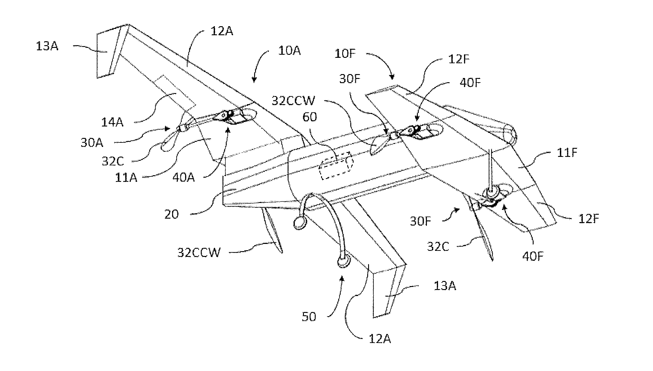
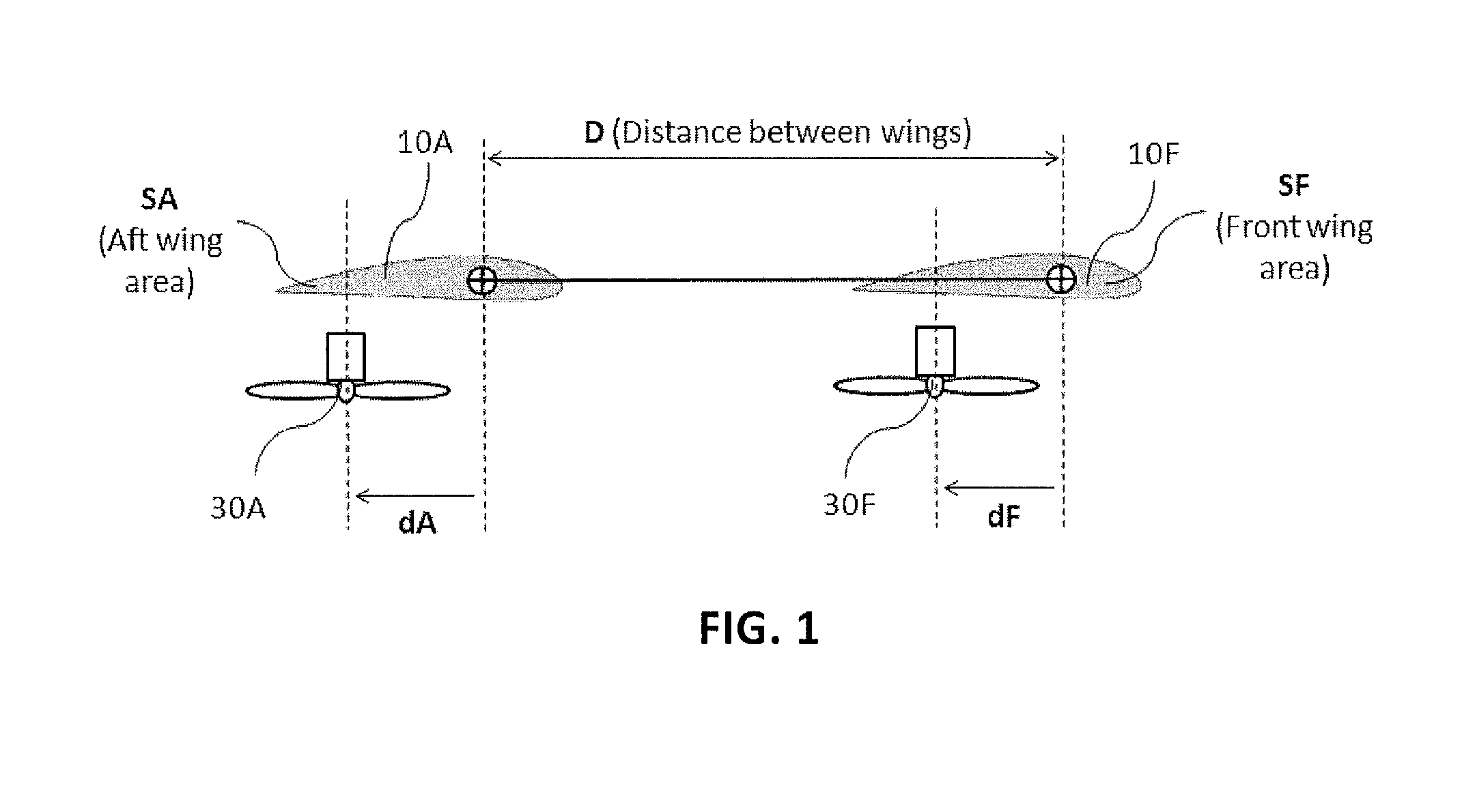
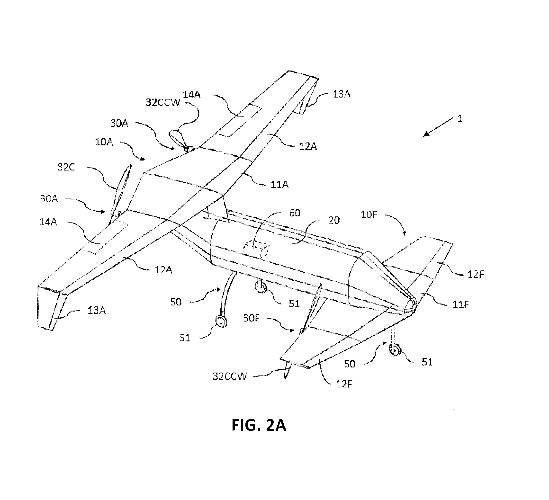
[0037]The description of illustrative embodiments according to principles of the present disclosure is intended to be read in connection with the accompanying drawings, which are to be considered part of the entire written description. In the description of embodiments of the invention disclosed herein, any reference to direction or orientation is merely intended for convenience of description and is not intended in any way to limit the scope of the present invention. Relative terms such as “lower,”“upper,”“horizontal,”“vertical,”“above,”“below,”“up,”“down,”“top” and “bottom” as well as derivative thereof (e.g., “horizontally,”“downwardly,”“upwardly,” etc.) should be construed to refer to the orientation as then described or as shown in the drawing under discussion. These relative terms are for convenience of description only and do not require that the apparatus be constructed or operated in a particular orientation unless explicitly indicated as such. Terms such as “attached,”“aff...


PUM


Abstract

The present disclosure relates to a high performance Vertical Takeoff and Landing (VTOL) aircraft for executing hovering flight, forward flight, and transitioning between the two in a stable and efficient manner. The VTOL aircraft provides a highly stable, controllable and efficient VTOL aircraft. The preferred comprises: (1) a pusher propeller configuration with strategic placement which maximizes the effective use of thrust, (2) four propellers which allow for the highly-controllable and mechanically simple control methods used in multirotor aircraft, (3) electric motors which create mechanically simple, lightweight and reliable operation, (4) and a tandem wing configuration which is stable, controllable and efficient in both hovering and forward flight. The VTOL aircraft is capable of full runway, short runway or vertical takeoffs or landings, having unobstructed forward view for camera and sensor placement; and providing a compact, mechanically simple and low-maintenance VTOL aircraft design.

Description

CROSS-REFERENCE TO RELATED APPLICATION[0001]This application claims the benefit of U.S. provisional patent application Ser. No. 62 / 006,977 filed on Jun. 3, 2014STATEMENT REGARDING FEDERALLY SPONSORED RESEARCH AND DEVELOPMENT[0002]N / ABACKGROUND OF THE INVENTION[0003]1. Field of the Invention[0004]The present invention relates to a Vertical Takeoff and Landing (VTOL) aircraft, more particularly to a high performance VTOL aircraft for executing hovering flight, forward flight, and transitioning between the two in a stable and efficient manner.[0005]2. Discussion of the Background[0006]Vertical Takeoff and Landing (VTOL) aircraft is an aircraft can take off, hover, transition to forward flight, and land vertically. Many designs had been proposed for several years. One of the main challenges of this type of aircraft design relates to the relative placement of propulsion units and wings in order to minimize interference such as the slipstream of the propulsion units hitting the wings thus...

Claims


Application Information

Patent Timeline
Patent Type & Authority Applications(United States)
IPC IPC(8): B64C29/00
CPCB64C29/0033B64C39/024B64C39/12B64U70/80B64U10/25B64U50/19
Inventor CRUZ AYOROA, JUAN GABRIEL
Owner HYUNDAI MOTOR CO LTD
Why Eureka
Try Eureka