Connector attached optical fiber unit and optical connector boot

a technology of optical fiber and connector, which is applied in the direction of optics, fibre mechanical structures, instruments, etc., can solve the problems of limited bending or drawing of the optical fiber extending from the mt connector supported by the substrate in the direction along the surface of the substrate, and the optical fiber inside the boot in the direction of the boot width direction, and the inability to bend the boo

Active Publication Date: 2015-12-03
THE FUJIKURA CABLE WORKS LTD
View PDF36 Cites 27 Cited by
  • Summary
  • Abstract
  • Description
  • Claims
  • Application Information

AI Technical Summary

Benefits of technology

[0031]According to the connector attached optical fiber unit of the aspects of the present invention, it is possible to bend the tubular body portion of the boot attached to the MT connector along with the plurality of optical fibers accommodated...

Problems solved by technology

However, in this case, bending or drawing of the optical fiber extending from the MT connector supported by the substrate in the direction along the surface of the substrate is largely limited.
However, in the boot having a flat tubular shape disc...

Method used


Image

  • Connector attached optical fiber unit and optical connector boot
  • Connector attached optical fiber unit and optical connector boot
  • Connector attached optical fiber unit and optical connector boot

Examples


first embodiment

[0053]A first embodiment of the present invention will be described with reference to FIGS. 1 to 6.

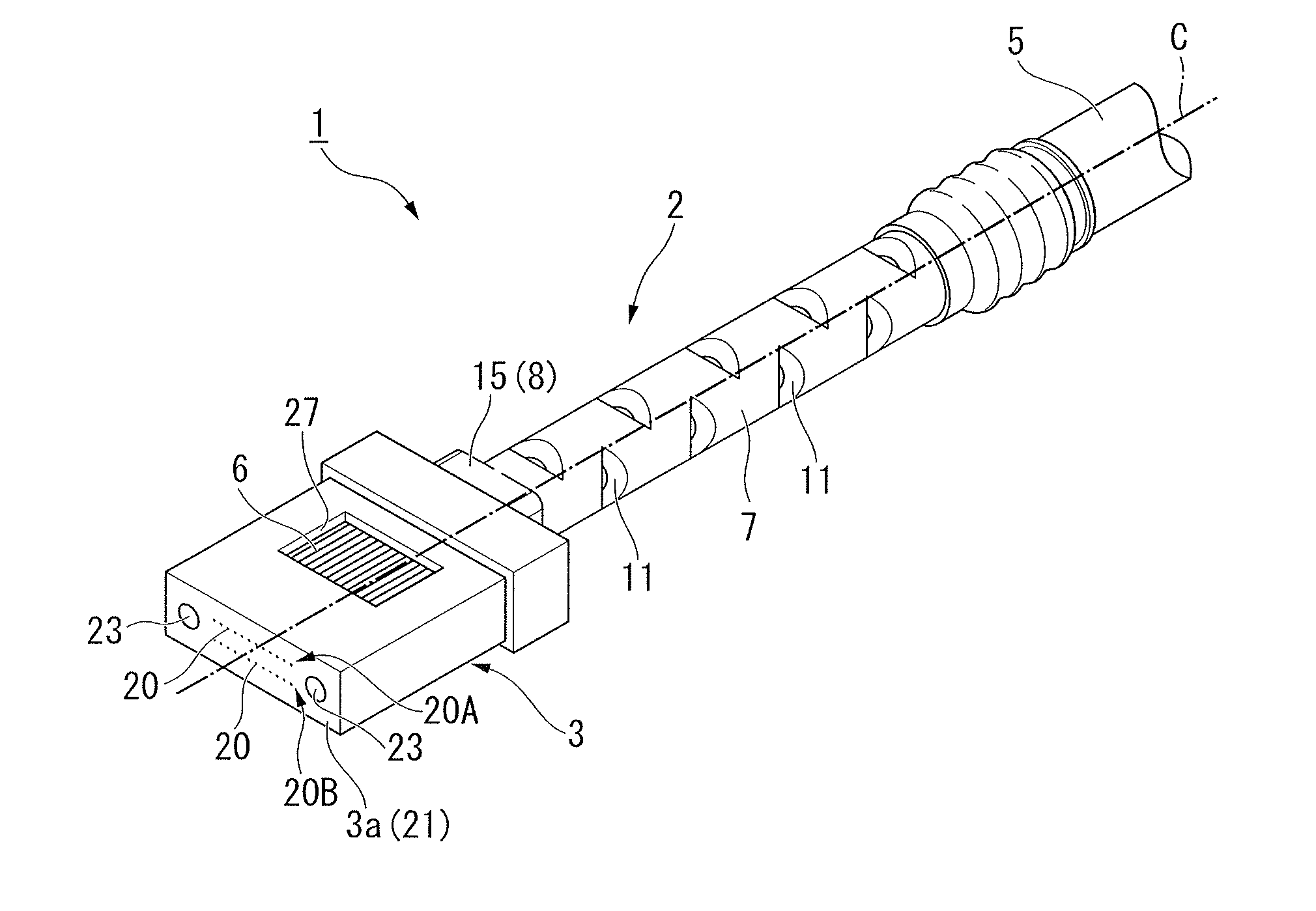
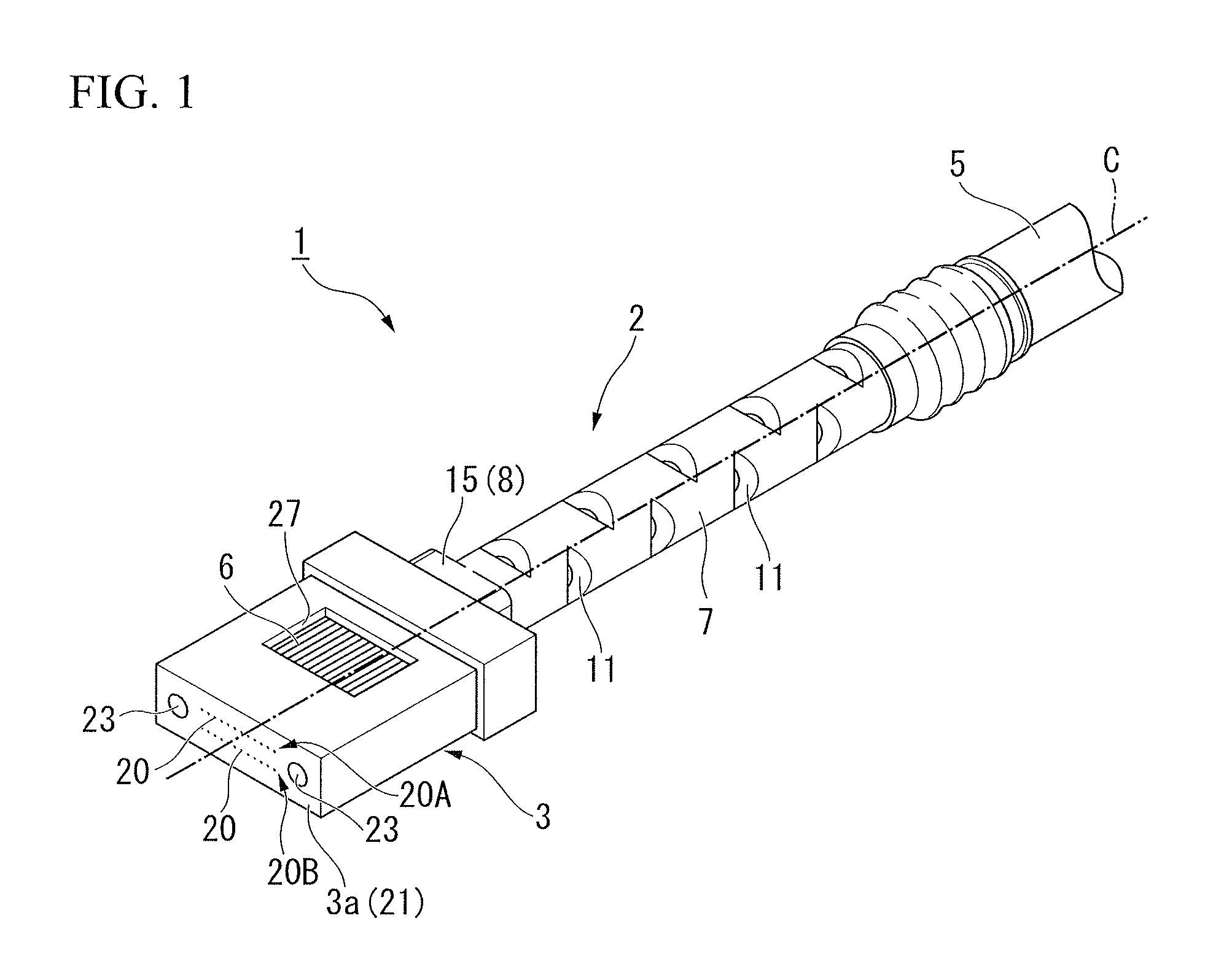
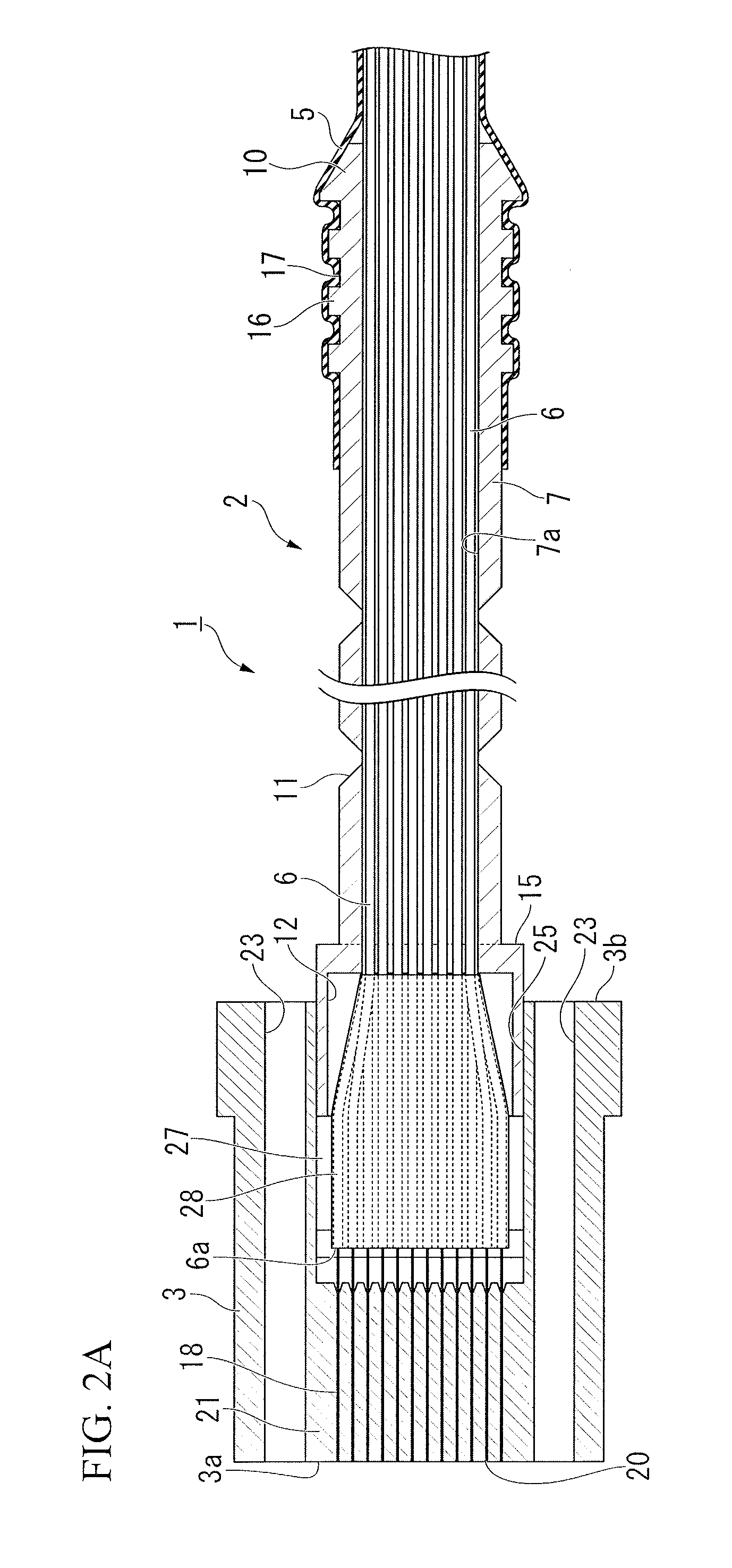
[0054]As shown in FIGS. 1 to 2B, a connector attached optical fiber unit 1 of the present embodiment includes an MT optical connector 3 (hereinafter, also referred to a “MT connector”), a tubular optical connector boot 2 (hereinafter, simply referred to as a “boot”) which has a front end portion inserted into and fixed to the MT connector 3 and is attached to the MT connector 3, and a protection tube 5 which is externally inserted and fixed to the rear end portion of the boot 2.

[0055]The connector attached optical fiber unit 1 is configured to accommodate a plurality of optical fibers 6, which include tip portions inserted into and fixed to the MT connector 3 and extend to the rear side opposite to a joining end surface 3a of the front end from the MT connector 3, inside the boot 2 and the protective tube 5.

[0056]In this embodiment, the optical fiber wire 6 is an optical fiber. Hereina...

second embodiment

[0107]Next, a second embodiment will be described with reference to FIGS. 9 to 10B.

[0108]In addition, the same reference numerals are assigned to the same components as in the above-described first embodiment, and descriptions thereof are omitted.

[0109]Differences between the second embodiment and the first embodiment are that a tubular body portion 51 of an optical connector boot 50 according to the present embodiment is formed in a square cylindrical shape, and the notch portions 52 are disposed on only the side surfaces of the tubular body portion 51 of the rectangular cross-sectional longitudinal direction side of the front end insertion portion 13.

[0110]As shown in FIG. 10A the cross-sectional shape with respect to the center axis C of the tubular body portion 51 is formed in a square. Accordingly, a hole portion 52A formed by the notch portion 52 becomes a rectangular shape.

[0111]A head portion 53 has the same configuration as the front end insertion portion 8 of the boot 2 ac...

third embodiment

[0114]Next, a third embodiment will be described with reference to FIGS. 11 to 12B.

[0115]Moreover, the same reference numerals are assigned to the same components as in the above-described embodiments, and descriptions thereof are omitted.

[0116]Differences between the third embodiment and the first embodiment are that the optical connector boot 60 according to the present embodiment is formed to be used not for twelve cores but for eight cores.

[0117]The length in the rectangular cross-sectional longitudinal direction of the front end insertion portion 62 is shorter than the length in the rectangular cross-sectional longitudinal direction of the front end insertion portion 13 in the boot 2 according to the first embodiment. Similarly, also in the front fiber hole 63, the size in the rectangular cross-sectional longitudinal direction of the front end insertion portion is formed to be smaller than the size of the front fiber hole 12.

[0118]On the other hand, the outline of the abutting ...


PUM


Abstract

A connector attached optical fiber unit includes: an MT optical connector which includes a joining end surface formed at a front end of the MT optical connector and a hollow portion opened to a rear end surface opposite to the joining end surface; a tubular boot which includes a front end insertion portion inserted and fixed into to the hollow portion and a tube attachment portion formed at a rear end portion of the tubular boot, the tubular boot extending to a rear side from the MT optical connector; a protection tube into which the tube attachment portion is inserted and to which the tube attachment portion is fixed; and a plurality of optical fibers which include tip portions inserted and fixed into the MT optical connector and are accommodated inside the boot and the protection tube.

Description

BACKGROUND OF THE INVENTION[0001]1. Field of the Invention[0002]The present invention relates to a connector attached optical fiber unit in which a plurality of optical fibers having tip portions inserted into and fixed to an MT optical connector pass inside a boot attached to the MT optical connector, and an optical connector boot which is suitably used for the boot of the connector attached optical fiber unit.[0003]Priority is claimed on Japanese Patent Application No. 2014-111242, filed on May 29, 2014, the content of which is incorporated herein by reference.[0004]2. Description of Related Art[0005]An MT optical connector (based on F12 type optical connector of ESC 5981 and MT: Mechanically Transferable) is known as a multi-core optical connector which can cover the end of an optical fiber tape (a tape-like multi-core optical fiber such as an optical fiber tape core wire) so as to be connectable by a connector.[0006]The MT optical connector (hereinafter, also referred to as an M...

Claims


Application Information

Patent Timeline
IPC IPC(8): G02B6/38G02B6/44
CPCG02B6/3887G02B6/3826G02B6/443G02B6/4435G02B6/3885G02B6/38875G02B6/3861
Inventor KATO, SEIJI
Owner THE FUJIKURA CABLE WORKS LTD
Why Eureka
Try Eureka