Eureka AIR delivers breakthrough ideas for toughest innovation challenges, trusted by R&D personnel around the world.

Vehicle diagnostic data collecting apparatus, vehicle diagnostic data collecting method, vehicle diagnostic machine, and vehicle diagnosing method

Active Publication Date: 2015-12-03
HONDA MOTOR CO LTD
View PDF2 Cites 22 Cited by
  • Summary
  • Abstract
  • Description
  • Claims
  • Application Information

AI Technical Summary

Benefits of technology

The present invention aims to provide a system and method for collecting diagnostic data from a vehicle. The invention reduces the number of steps required for setting data collection settings and prevents errors in data collection. The system includes a data collecting apparatus that carries out some of the settings, reducing the effort of the operator. Additionally, the system identifies the target ECU and sets the corresponding collection items, reducing the likelihood of human error. Overall, the invention simplifies the process of collecting diagnostic data from a vehicle.

Problems solved by technology

Therefore, there is a concern that a great deal of effort (man-hour) is needed for this kind of setting operation, and there also is a concern that incorrect settings may occur due to human error.

Method used


Image

  • Vehicle diagnostic data collecting apparatus, vehicle diagnostic data collecting method, vehicle diagnostic machine, and vehicle diagnosing method
  • Vehicle diagnostic data collecting apparatus, vehicle diagnostic data collecting method, vehicle diagnostic machine, and vehicle diagnosing method
  • Vehicle diagnostic data collecting apparatus, vehicle diagnostic data collecting method, vehicle diagnostic machine, and vehicle diagnosing method

Examples


embodiment

A. Embodiment

1. Configuration

(1-1. Overall Configuration)

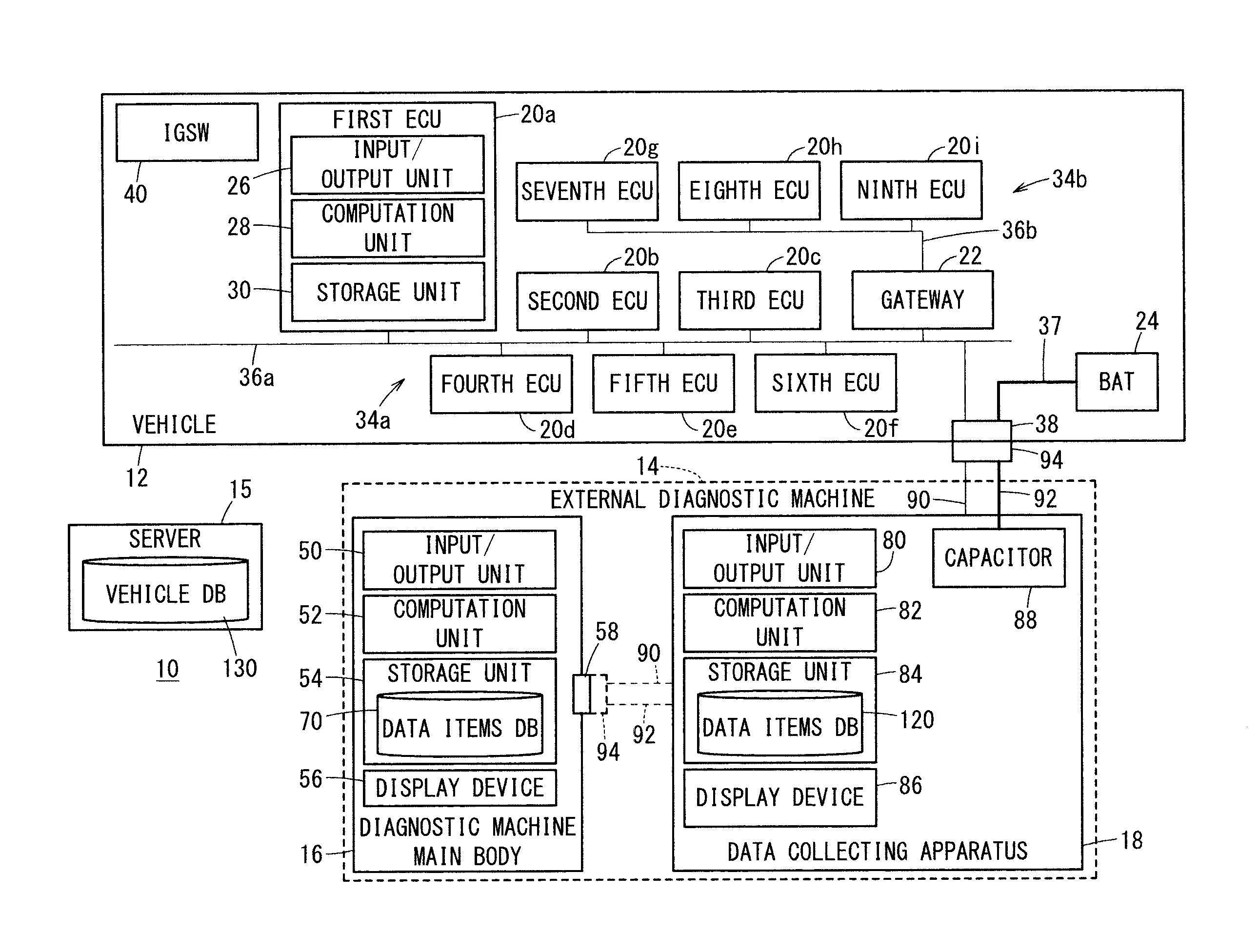
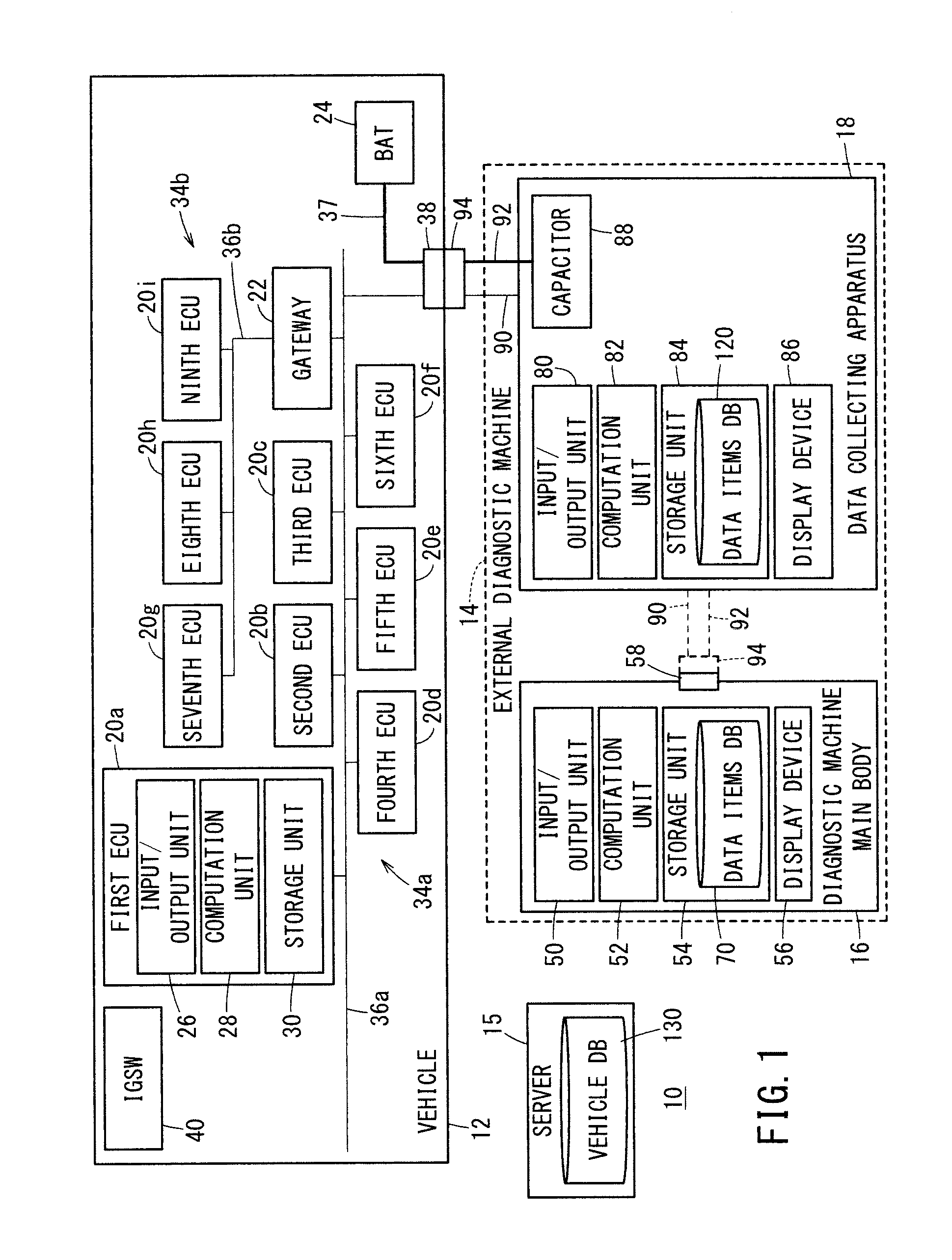
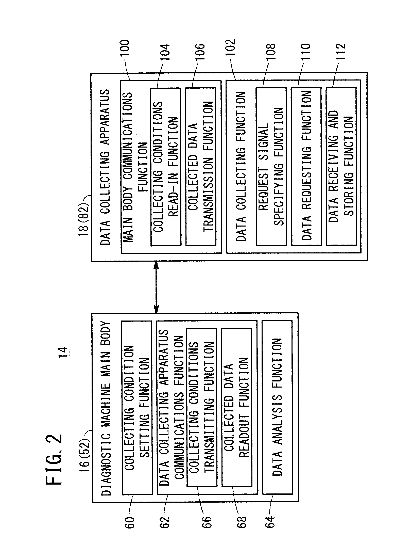
[0041]FIG. 1 is a block diagram showing an outline configuration of a diagnostic system 10 (hereinafter also referred to as a “system 10”) including a data collecting apparatus 18 according to an embodiment of the present invention. The system 10 includes a vehicle 12 that serves as a target object, an external diagnostic machine (vehicle diagnostic machine) 14 that carries out a fault diagnosis on the vehicle 12 from outside of the vehicle 12, and a server 15 that supplies information of the vehicle 12 to the external diagnostic machine 14. The external diagnostic machine 14 includes a diagnostic machine main body 16 (hereinafter also referred to as a “main body 16”) and a data collecting apparatus 18 (data logger).

(1-2. Vehicle 12)

[0042]The vehicle 12 of the present embodiment is a four-wheeled vehicle in the form of a hybrid vehicle having a driving engine and a traction motor (neither of which are shown). Alternatively, th...


PUM


Abstract

A data collecting apparatus sets types of target ECUs, and stores, in a storage unit, driving parameter data items, which are capable of being output by a plurality of ECUs, in association with IDs of the plurality of ECUs. Subsequently, for each of the aforementioned types, a query is made to a vehicle as to whether an installed ECU exists, and the installed ECU is identified as a target ECU. Thereafter, based on the ID of the installed ECU, driving parameter data items capable of being output by the installed ECU that was identified as the target ECU are set as collection items.

Description

CROSS-REFERENCE TO RELATED APPLICATIONS[0001]This application is based upon and claims the benefit of priority from Japanese Patent Applications No. 2014-114864 filed on Jun. 3, 2014 and No. 2014-114870 filed on Jun. 3, 2014, the contents all of which are incorporated herein by reference.BACKGROUND OF THE INVENTION[0002]1. Field of the Invention[0003]The present invention relates to a vehicle diagnostic data collecting apparatus, a vehicle diagnostic data collecting method, a vehicle diagnostic machine, and a vehicle diagnosing method.[0004]2. Description of the Related Art[0005]In the event that abnormal conditions are generated during driving of a vehicle, notification to the driver is performed through warnings by illuminating a warning lamp or the like that is provided on an instrument panel. Together with such abnormal conditions or the warnings that accompany the same, the user brings the vehicle to a dealer or a repair facility where diagnostic operations or repairs on the ve...

Claims


Application Information

Patent Timeline
IPC IPC(8): G07C5/08
CPCG07C5/0808G07C5/0858G07C5/008G07C2205/02
Inventor OHNO, TETSUYAUCHIDA, MAKOTO
Owner HONDA MOTOR CO LTD
Why Eureka
Eureka Blog
Learn More