
Endoscope operating apparatus

a technology of operating apparatus and endoscope, which is applied in the field of improving an endoscope operating apparatus, can solve the problems of increasing the number of parts of the bending holding mechanism, the difficulty of operation, so as to reduce the weight of the whole operating part, reduce the number of constituent parts, and simplify the configuration of the operating apparatus

Inactive Publication Date: 2015-12-10
SG ENDOSCOPY
View PDF3 Cites 13 Cited by
  • Summary
  • Abstract
  • Description
  • Claims
  • Application Information

AI Technical Summary

Benefits of technology

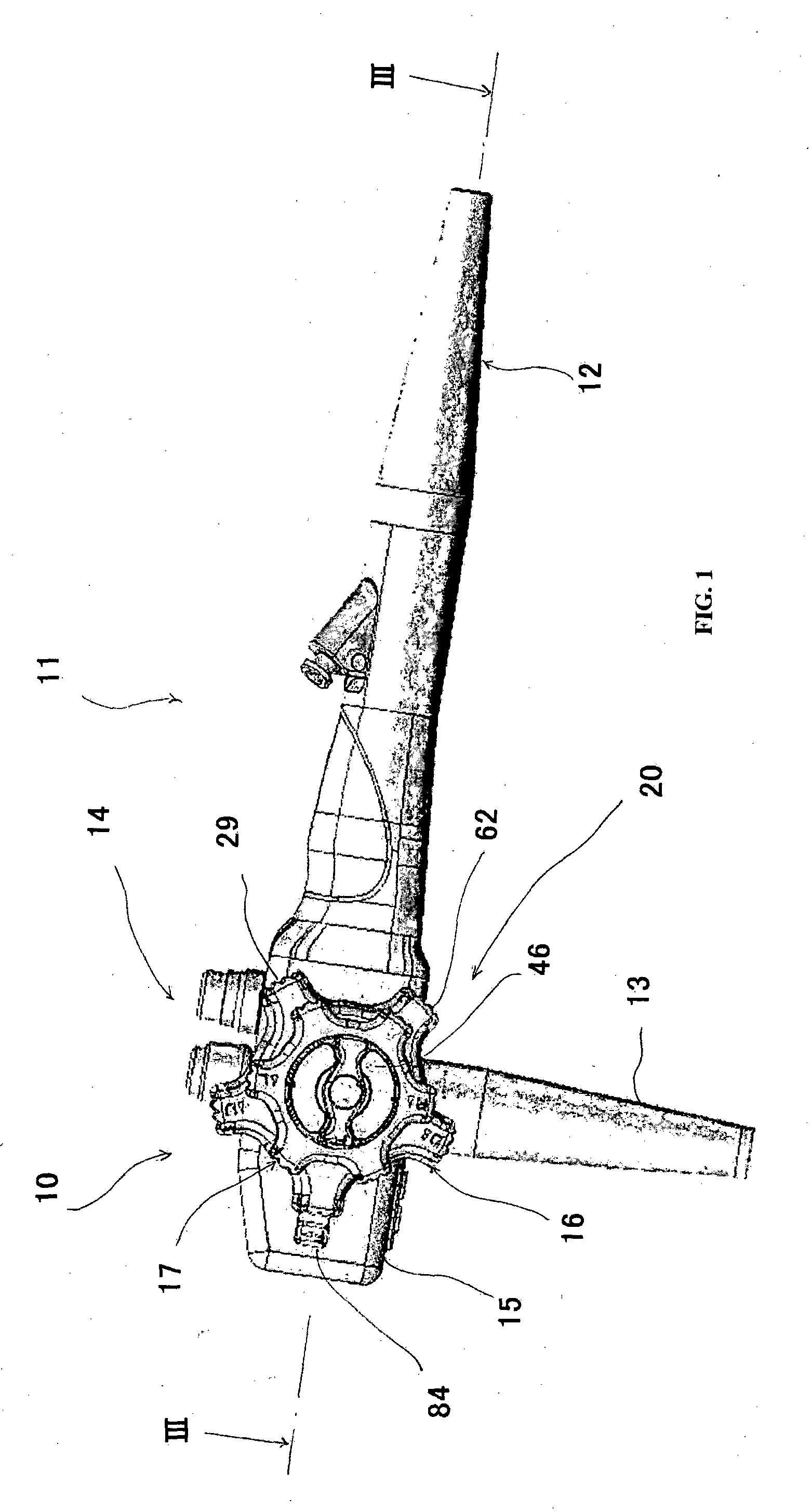
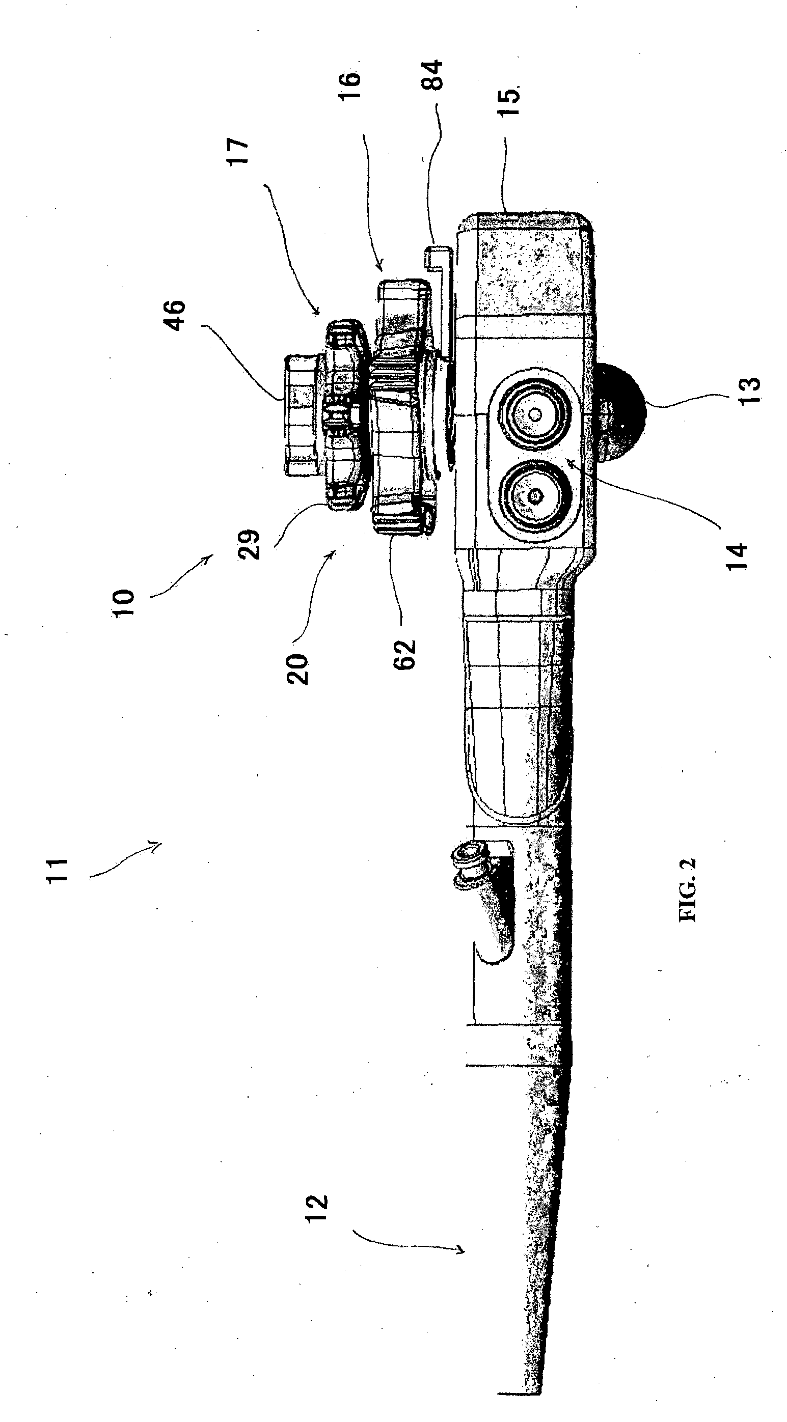
The invention is related to an endoscope operating apparatus, with a lock mechanism that can select three positions: half-lock, lock, and free. The lock operating part has an operating handle that can rotate, and a position defining member with recessed portions that indicate the different positions. The engagement member is a rod-shaped member that engages the recessed portions on the position defining member by rotating the operating handle. This allows for easy and secure operation of the endoscope, with proper clicking feedback for the lock, half-lock, and free positions. The biasing force of the rod-shaped member can be adjusted to different operator preferences, and the position defining member can be a cylindrical member or a plate-shaped member.

Problems solved by technology

In the above conventional art, however, since such a configuration is adopted that the leaf spring for clicking is formed in an approximately C shape in plan view, the convex portions are formed in the vicinity of the discontinuity portion, and these two convex portions get over four projections simultaneously, the whole configuration of the bending holding mechanism is considerably complicated and the number of parts for the bending holding mechanism is increased.
Further, since the configuration is adopted where the two convex portions get over four projections simultaneously, there is such a possibility that any of the convex portions is caught by any of the projections, which results in difficulty in operation.
In such an endoscope, however, since a lot of constituent parts are required, there is such a drawback that a structure becomes complicated, which results in increase of a manufacture cost.
Further, since the number of constituent parts is increased and the function is complicated, a long time is required as an adjusting time of the endoscope.
In addition, since the weight of the whole operating part increases according to increase of the number of constituent parts, there is such a drawback that since an operator generally performs examination while holding the operating part with his / her one hand, examining work for a long time results in his / her pain.

Method used


Image

  • Endoscope operating apparatus
  • Endoscope operating apparatus
  • Endoscope operating apparatus

Examples


second embodiment

[0110]FIG. 11 to FIG. 13 show the endoscope operating apparatus 10 according to the present invention.

[0111]An endoscope operating apparatus 112 according to the second embodiment is different from the endoscope operating apparatus 10 according to the first embodiment in configuration of the lock operating part 84 on the side of the vertical-direction operating handle. Incidentally, same members as those of the first embodiment are attached with same reference numerals, and explanation thereof is omitted.

[0112]In the second embodiment, a leaf spring pressure adjusting mechanism 111 configured such that a pressure contacting force of an engagement projection portion 117 to the position defining member 87 can be adjusted by changing a spring constant of a leaf spring member 102 provided in a lock operating handle 113 appropriately.

first embodiment

[0113]The leaf spring pressure adjusting mechanism 111 is composed of the leaf spring member 102 which is constituted as a member separated from an arm part 114, which is different from the first embodiment, and whose proximal end portion is fixed to an upper face of the arm part 114 along a widthwise direction by screws (not shown), and a spring constant adjusting member 103 covering about a half of the leaf spring member 102 and arranged on an upper face portion of the arm part 114 so as to be movable along the lengthwise direction of the arm part 114.

[0114]As shown in FIG. 13, in the lock operating handle 113 according to this embodiment, a leaf spring member mounting part 115 formed in a flat rectangular shape recessed from an upper face of the arm part 114 over a widthwise whole area is formed on the proximal end portion of the arm part 114.

[0115]Screw holes 116 and 116 for fixation of the leaf spring member 102 to the arm part 114 are formed on one end portion of the leaf spri...

third embodiment

[0131]As shown in FIG. 15, the lock operating part 127 is composed of a lock operating handle 128 formed in an approximately short cylindrical shape as a whole and provided with a rotation part 129 having an engagement part 131 and an arm part 130 provided so as to protrude from a circumferential face of the rotation part 129 integrally, and a position defining member 121 fixed to an upper face portion of the gear box 26 and arranged in a space within the rotation part 129 in a lower portion of the rotation part 129.

[0132]The position defining member 121 is fixed to the upper face portion of the gear box 26 by screws 123 in a state where the center shaft 27, the horizontal-direction drive shaft 28 and the vertical-direction drive shaft 61 have penetrated the position defining member 121.

[0133]As shown in FIG. 15, the position defining member 121 is integrally formed as an approximately-disc member wholly, and it is composed of a large-diameter base portion 124, a small-diameter dis...


PUM


Abstract

To provide an endoscope operating apparatus where an operator who is a user can recognize a locked state and a free state clearly with his / her fingers grasping an operating part under an examining environment, and the number of constituent parts can be decreased to reduce a manufacturing cost and achieve weight reduction. An operating apparatus of an endoscope which is provided with a flexible tube inserted into a body to be examined and having a bending part at a distal end thereof and which performs work by bending the bending part according to a manual operation, comprising: a drive part which can pull a wire which is disposed in the flexible tube, a distal end of the wire being fixed to the bending part and the wire bending the bending part; and an operating part which operates the drive part.

Description

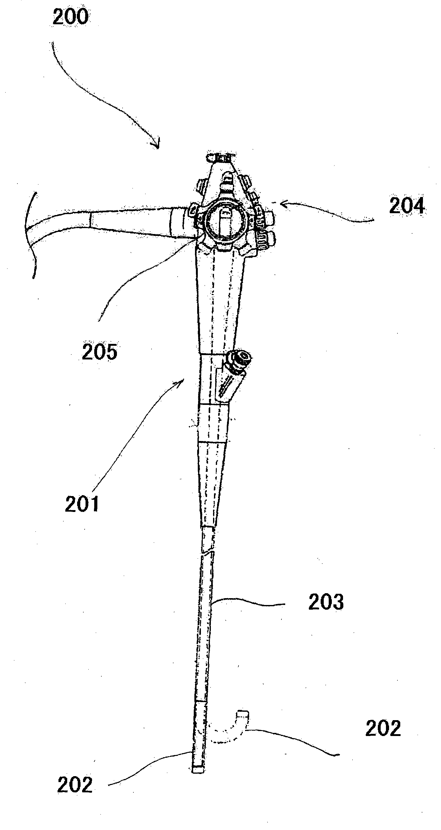
TECHNICAL FIELD[0001]The present invention relates to improvement of an endoscope operating apparatus.BACKGROUND ART[0002]Conventionally, endoscopes are used in a medical field or the like in order to perform examination, curing, or the like. As shown in FIG. 17, such an endoscope 200 is provided with a main body 201 and a flexible tube 203 which is joined to the main body 201, is inserted into a person to be examined, and has a bending part 202 at a distal end of the flexible tube 203, and the main body 201 is provided with an operating part 204 which can bend the bending part 202 provided at the distal end portion of the flexible tube 203 appropriately.[0003]A wire (not shown) whose distal end is fixed to the bending part 202 and pulls the bending part 202 to bend the same is arranged within the flexible tube 203, and examination, curing and the like are performed by driving the wire in a pulling fashion by a proper means to bend the bending part 202 upward, downward, leftward or ...

Claims


Application Information

Patent Timeline
Patent Type & Authority Applications(United States)
IPC IPC(8): A61B1/005
CPCA61B1/0057A61B1/0055A61B1/0052A61B1/00042
Inventor FAN, JIN MEI
Owner SG ENDOSCOPY
Learn More