Track-guided vehicle, and car body tilt control method therefor

Active Publication Date: 2015-12-10
MITSUBISHI HEAVY IND ENG LTD
View PDF12 Cites 21 Cited by
  • Summary
  • Abstract
  • Description
  • Claims
  • Application Information

AI Technical Summary

Benefits of technology

[0031]In the guide-rail track vehicle according to these aspects of the present invention, it is possible to m

Problems solved by technology

However, since an unbalanced centrifugal force increases corresponding to an increase in travel spee

Method used


Image

  • Track-guided vehicle, and car body tilt control method therefor
  • Track-guided vehicle, and car body tilt control method therefor
  • Track-guided vehicle, and car body tilt control method therefor

Examples


first embodiment

[0055]Hereinafter, a guide-rail track vehicle 1 in the present invention will be described.

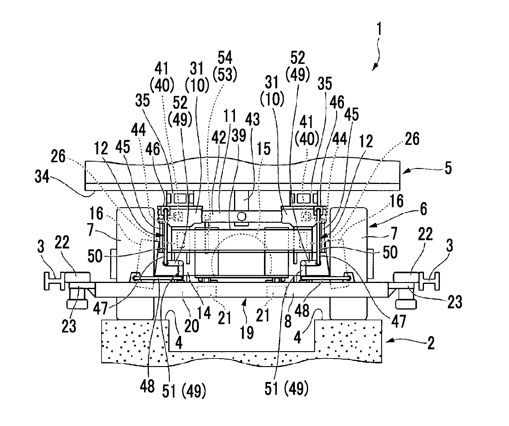
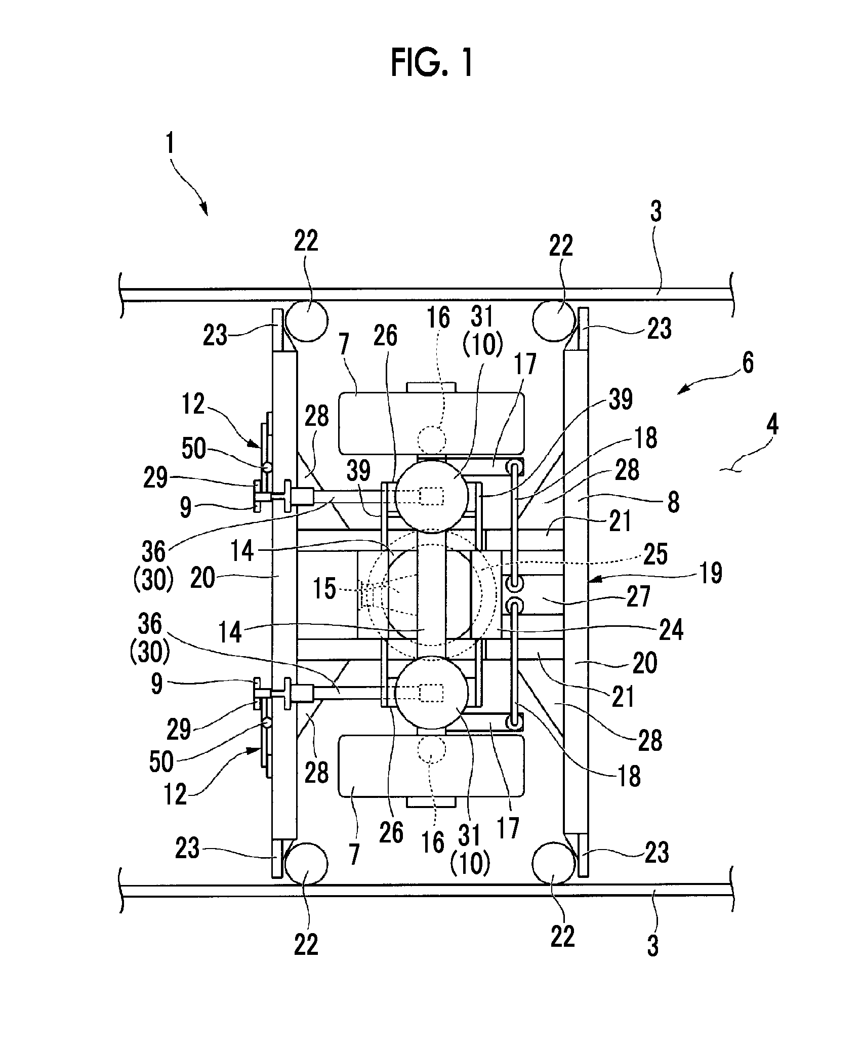
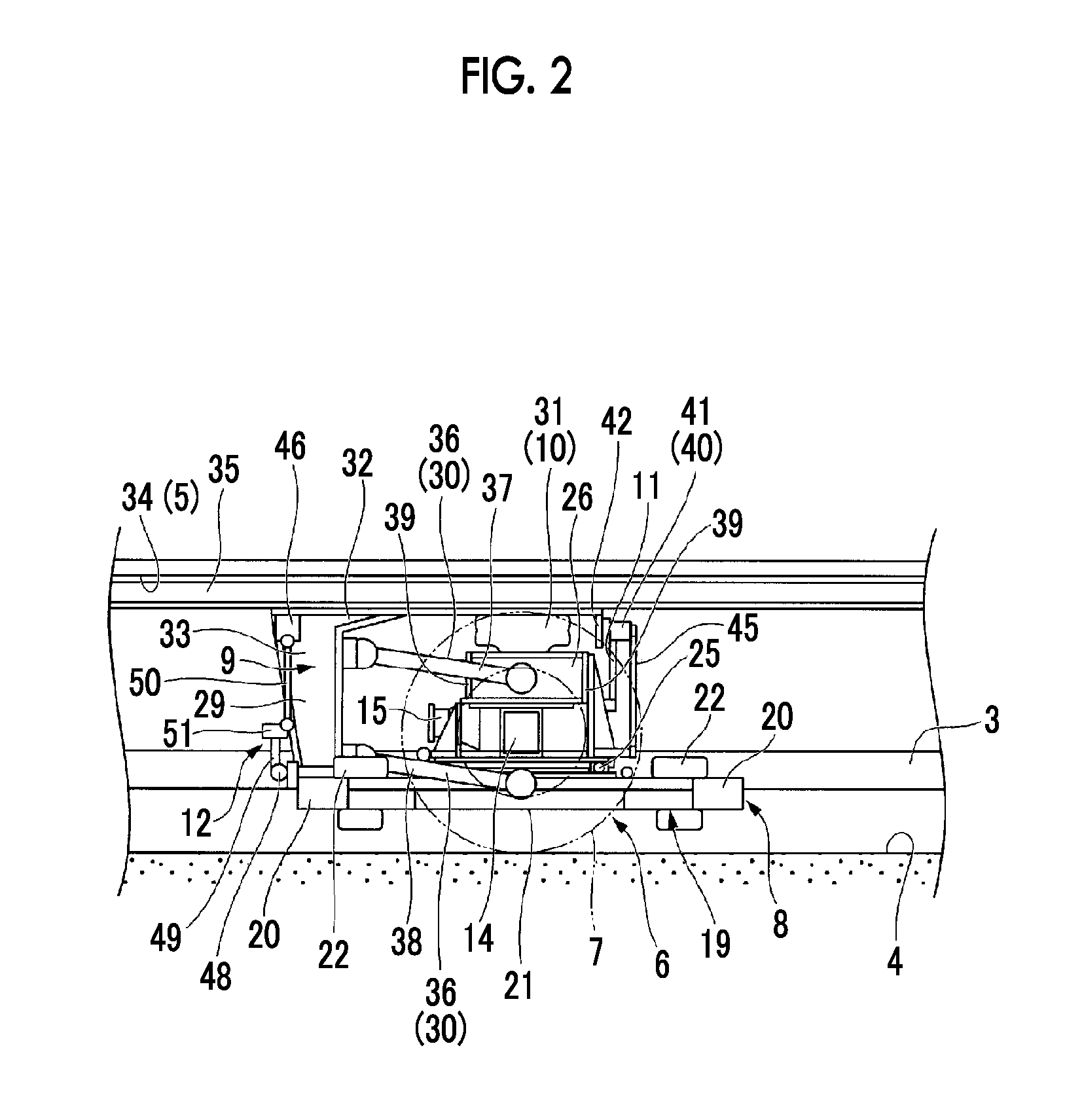
[0056]FIGS. 1 to 3 illustrate the guide-rail track vehicle 1 in the first embodiment. The guide-rail track vehicle 1 in the first embodiment travels on a travel path 4 while being guided by guide rails 3 which are so-called side guide rails and are disposed respectively in the opposite lateral side portions of a track 2.

[0057]As illustrated in FIGS. 1 to 3, the guide-rail track vehicle 1 includes a car body 5 and a bogie 6.

[0058]The car body 5 (refer to FIGS. 2 and 3) is formed in a rectangular parallelepiped hollow shape which is long in a longitudinal direction. The inner space of the car body 5 acts as a space for accommodating passengers.

[0059]The bogies 6 can travel on the travel path 4, and support bottoms of front and rear portions of the car body 5, respectively. The bogie 6 includes a pair of travelling wheels 7; a steering device 8; a suspension apparatus 9; a dampening apparatus 10;...

second embodiment

[0127]Accordingly, during a normal operation of the guide-rail track vehicle of the second embodiment, it is possible to automatically control the height of the air spring 31 using the leveling valve 41 and the adjustment rod 45 such that the car body 5 is not brought into a tilted state. In contrast, in order to tilt the car body 5, it is possible to individually adjust the height of each of the air springs 31 using the bypass pipe 65 and the second 3-way electromagnetic switching valve 64.

[0128]Since the height of each of the air springs 31 is adjusted by the bypass pipe 65 and the second 3-way electromagnetic switching valve 64 in a state where the leveling valve 41 is restricted from adjusting the height of the air spring 31, an operation of the leveling valve 41 can be prevented from disturbing the tilting of the car body 5. Accordingly, the respective heights of the air springs 31 are set to be different from each other, and thus the car body 5 is tilted. As a result, it is po...

sixth embodiment

[0179]Accordingly, in the guide-rail track vehicle of the sixth embodiment, it is possible to calculate the normal lateral acceleration, in which the cant of the track 2 is taken into consideration. For this reason, it is possible to calculate an optimal tilt angle required to tilt the car body 5 toward the inner rail when the vehicle rounds a curve.

[0180]Subsequently, a guide-rail track vehicle in a seventh embodiment of the present invention will be described. Since a partial configuration of a guide-rail track vehicle is the only difference between the third embodiment and the seventh embodiment, a description will be given with the same reference signs assigned to the same parts. The guide-rail track vehicle in the seventh embodiment includes the car body 5 and the bogie 6, and the bogie 6 includes a pair of the travelling wheels 7; the steering device 8; the suspension apparatus 9; the dampening apparatus 10; the car body tilting mechanism 11; the detection unit 12; and a tilt ...


PUM


Abstract

This track-guided vehicle is provided with a car body, and a bogie that supports the car body from the bottom, and has a frame capable of pivoting around an axis perpendicular to a track. The bogie is provided with: a car body tilting part that tilts the car body to the left and right in the direction of travel; a detection part that detects the amount of pivot of the frame; and a tilt control part that allows the car body to be tilted by the car body tilting part on the basis of the amount of pivot detected by the detection part.

Description

TECHNICAL FIELD[0001]The present invention relates to a guide-rail track vehicle that can travel along a track, and particularly, to a guide-rail track vehicle that can tilt a car body toward an inner rail and a car body tilt control method therefor.BACKGROUND ART[0002]A railway-based transportation system, which can travel on a track via travelling wheels with rubber tires, is known as a new transportation system other than a bus or a train. Typically, this type of railway-based transportation system is referred to as a “new transportation system” or an “automated people mover (APM)”. In the railway-based transportation system, guide wheels disposed respectively in the opposite side portions of a vehicle are guided by guide rails provided along the track.[0003]In many cases, the vehicle of the railway-based transportation system has a car body length shorter than that of a typical train vehicle, and thereby, similar to an automobile or a bus, the vehicle includes single-axle bogies...

Claims


Application Information

Patent Timeline
IPC IPC(8): B61F5/22B61F5/50
CPCB61F5/50B61F5/22B61B13/00B61F9/00
Inventor MAEYAMA, HIROYUKITAMURA, SOKATAHIRA, KOUSUKE
Owner MITSUBISHI HEAVY IND ENG LTD
Why Eureka
Try Eureka