

Hinge
- Summary
- Abstract
- Description
- Claims
- Application Information
AI Technical Summary
Benefits of technology
Problems solved by technology
Method used
Image

Examples
Embodiment Construction
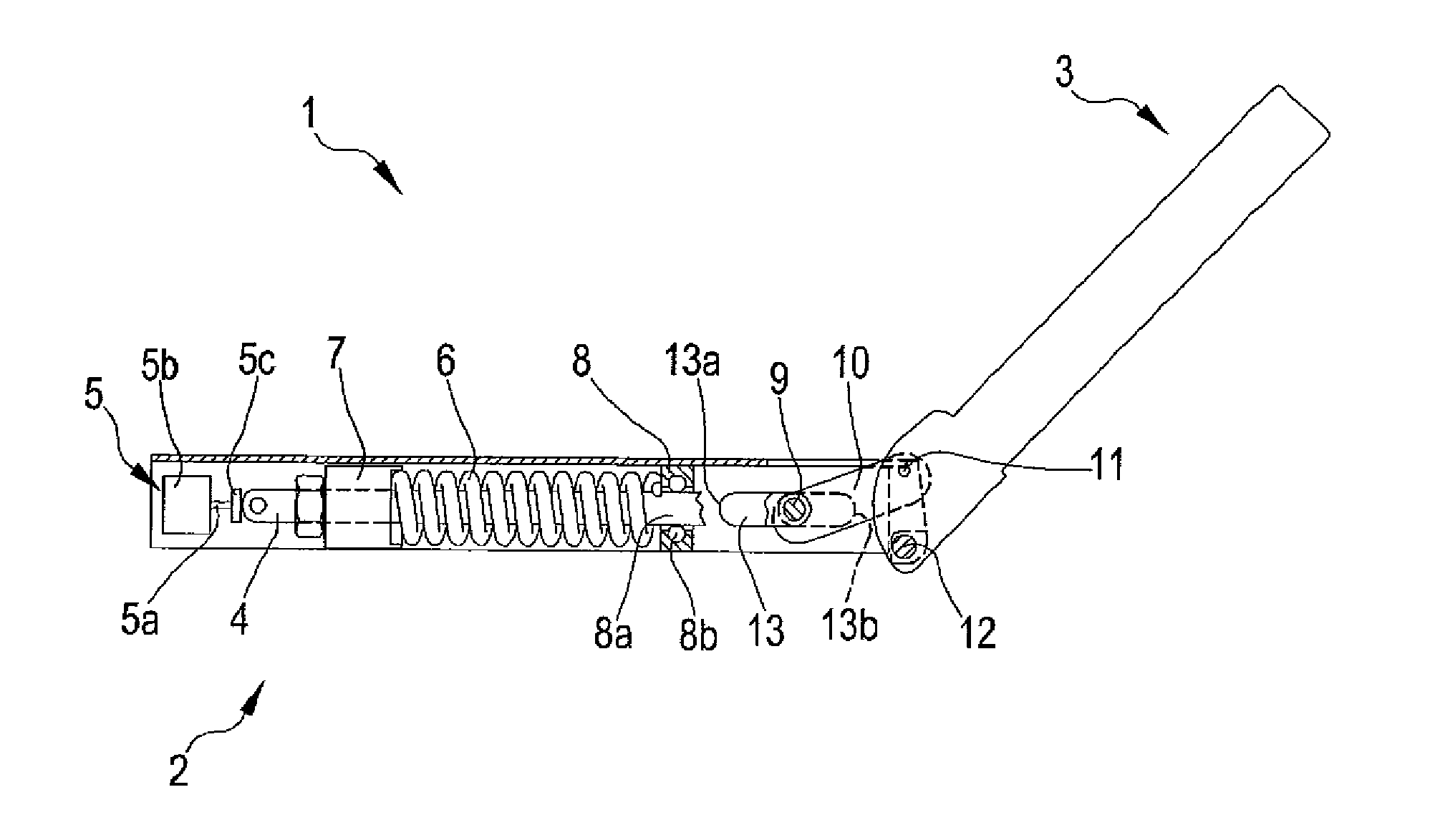
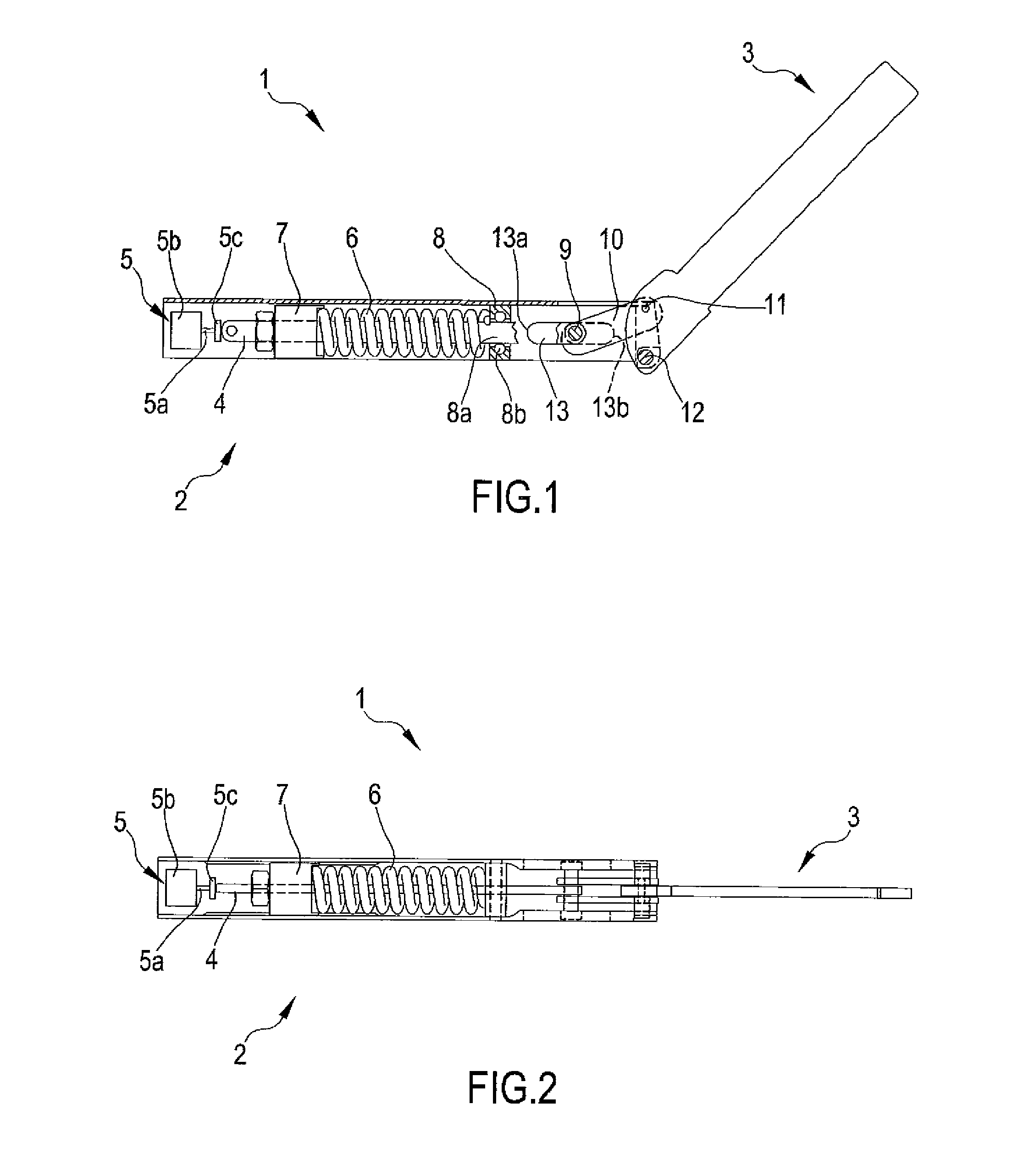
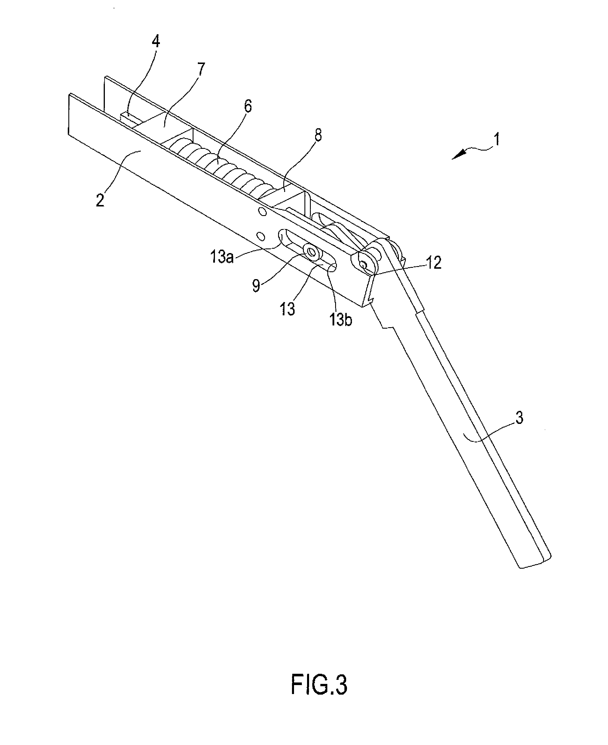
[0030]In the embodiment of the present invention shown herein, a hinge 1 for the door which covers at least in part a compartment, comprises a fixed support 2 coupled to the compartment frame, and a mobile support 3 coupled to the door. The mobile 3 and fixed 2 supports are rotatably constrained one to the other by means of the pin 12.
[0031]As known in the art, the door hinge 1 described herein is further provided with means 6 to impose a predefined law of motion to the mobile support 3 with respect to the fixed support 2. These usually mechanical means, allow to counter or aid the opening and / or closing of the door, and may comprise, for example, elastic means, means to dampen the motion, or means with guiding cam.
[0032]More particularly, the use of these means to impose a predefined law of motion to the mobile support 3 with respect to the fixed support 2, comprising the coil spring 6 in the hinge 1 shown herein, is intended to prevent the door from opening with an overspeed and / o...
PUM
 Abstract
Description
Claims
Application Information