
Downhole communications arrangement and downhole system

Active Publication Date: 2015-12-10
BAKER HUGHES INC
View PDF1 Cites 0 Cited by
  • Summary
  • Abstract
  • Description
  • Claims
  • Application Information

AI Technical Summary

Benefits of technology

This patent describes a way to communicate in a downhole environment using electromagnetic devices. A shield is used to prevent certain frequencies from passing through, but can be modified based on certain conditions to allow certain frequencies to pass through. This way, information can be sent and received in a safe and controlled way in the downhole environment.

Problems solved by technology

Such systems however are relatively expensive and unflexible in their application.

Method used


Image

  • Downhole communications arrangement and downhole system
  • Downhole communications arrangement and downhole system

Examples


Embodiment Construction

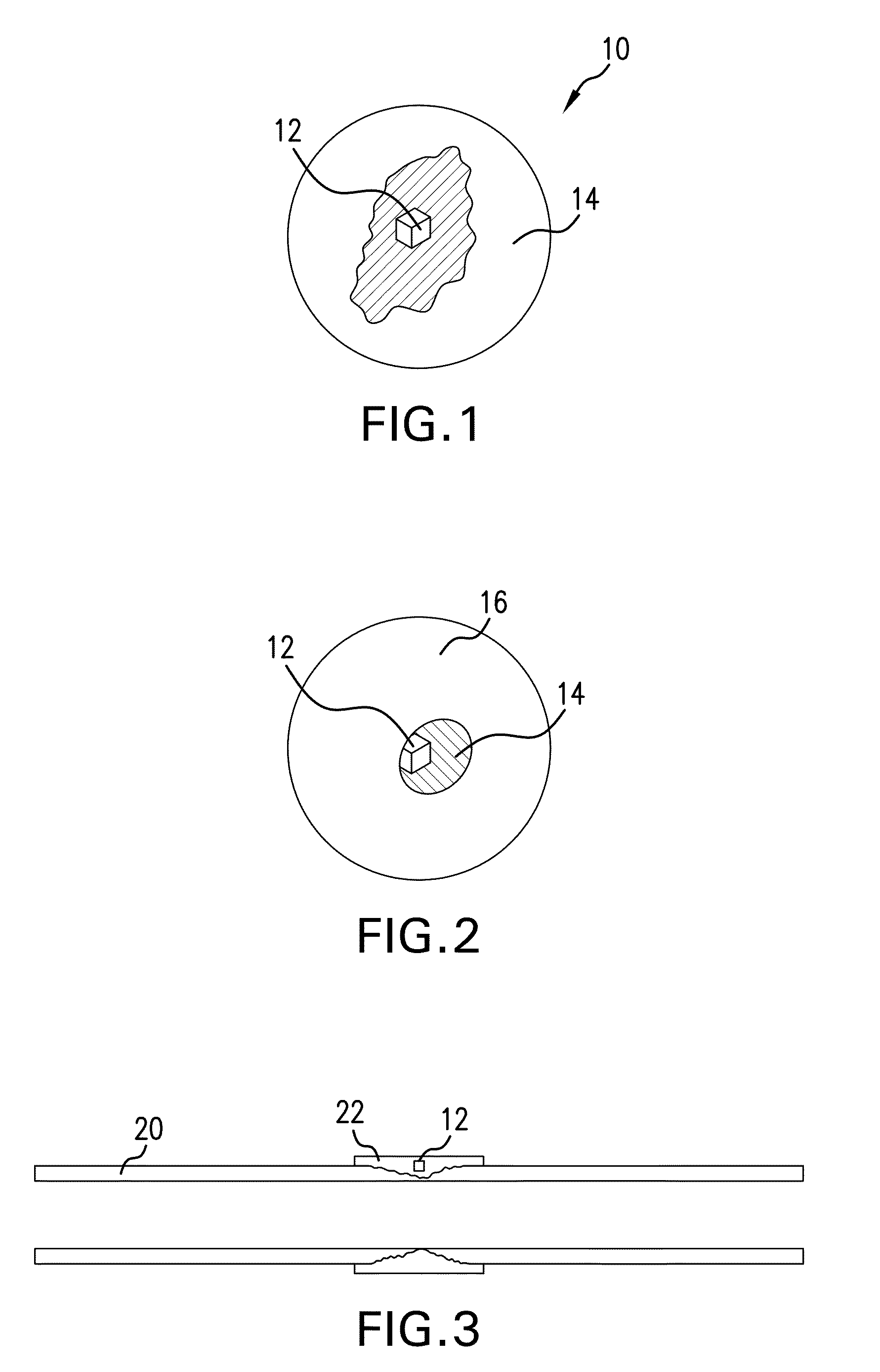
[0008]Referring to FIG. 1, a broad concept of the invention herein described is illustrated. The arrangement 10 includes one or more electromagnetic (EM) device(s) 12 each of which may be configured as a transmitter, a receiver, a transceiver or a reflector and a shield 14 that inhibits passage of at least one frequency of one or more frequencies that one or more EM device(s) use. Hereinafter “EM device” or “device” in the singular is intended to encompass the one or more devices disclosed above. The shield is configured to be alterable by one or more selected conditions in the downhole environment to allow passage of the one or more frequencies. The shield may completely envelop the EM device, as in FIG. 1, or may merely represent a small portion of a structure 16 (see FIG. 2) that envelopes the EM device 12. In the event that the shield 14 itself does not envelope the EM device 12, the structure 16 that does envelop the balance of the device is itself impervious to EM radiation or...


PUM


Abstract

A downhole communications arrangement including one or more electromagnetic (EM) devices; and a shield disposed relative to the one or more devices. The shield preventing or reducing passage of one or more EM frequencies and being alterable by one or more selected conditions to allow passage of the one or more frequencies. A method for communicating in a downhole environment.

Description

BACKGROUND[0001]In contemporary hydrocarbon exploration and recovery efforts, sensorial technology is more ubiquitous than ever. Traditional concept sensors and receivers have been used. Very important to successful downhole operations is effective receipt of information at decision making locations such as surface locations and controller locations. This is because modern downhole assemblies offer a number of refinements over those of the past in that undesirable occurrences downhole can be managed rapidly and in some cases even while a well is on production. Making such capabilities most efficient requires rapid and reliable communication from a sensory function to a command function. It will be recognized that there are a number of systems already available to sensing and transmitting information, for example, optic fiber based systems, electrical systems, etc. that sense selected parameters and transmit the information to a control center. Such systems however are relatively exp...

Claims


Application Information

Patent Timeline
IPC IPC(8): E21B47/12G01V3/30
CPCG01V3/30E21B47/122E21B47/13
Inventor WANG, KEXU, ZHIYUEJOHNSON, MICHAEL H.
Owner BAKER HUGHES INC
Learn More