Torque converter

a technology of torque converter and torque converter, which is applied in the direction of rotary clutches, fluid couplings, gearing, etc., can solve the problems of excessive load and impact not being applied, and achieve the effect of reducing the load

Active Publication Date: 2015-12-10
YUTAKA GIKEN CO LTD
View PDF2 Cites 4 Cited by
  • Summary
  • Abstract
  • Description
  • Claims
  • Application Information

AI Technical Summary

Benefits of technology

[0008]The present invention is made in the light of the above circumstances, and has an object to provide a torque convertor that can inhibit movement of a st...

Problems solved by technology

Therefore, an excessively large load and impact are not applied to the thrust bearings which are resp...

Method used


Image

  • Torque converter
  • Torque converter

Examples


Embodiment Construction

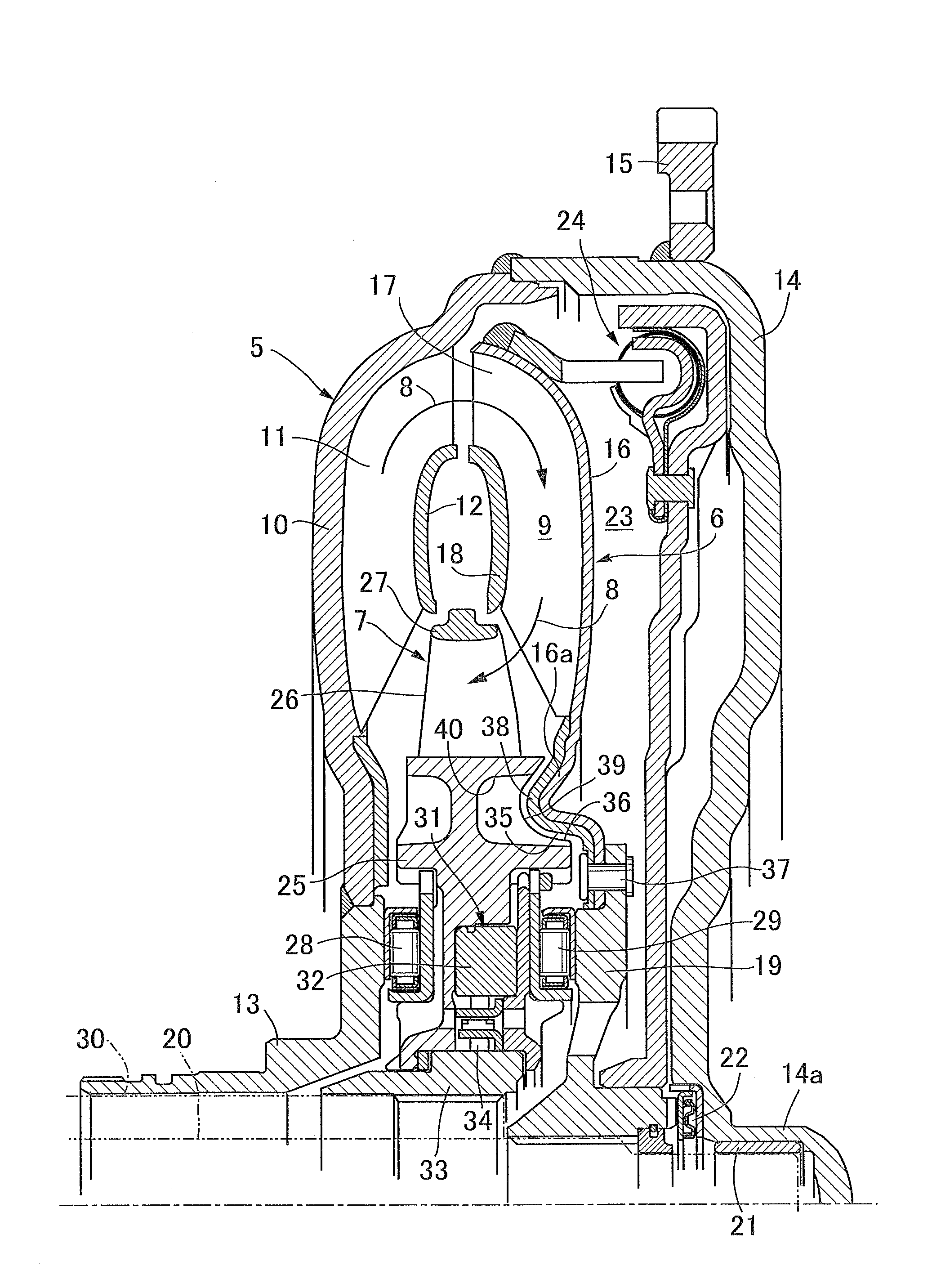
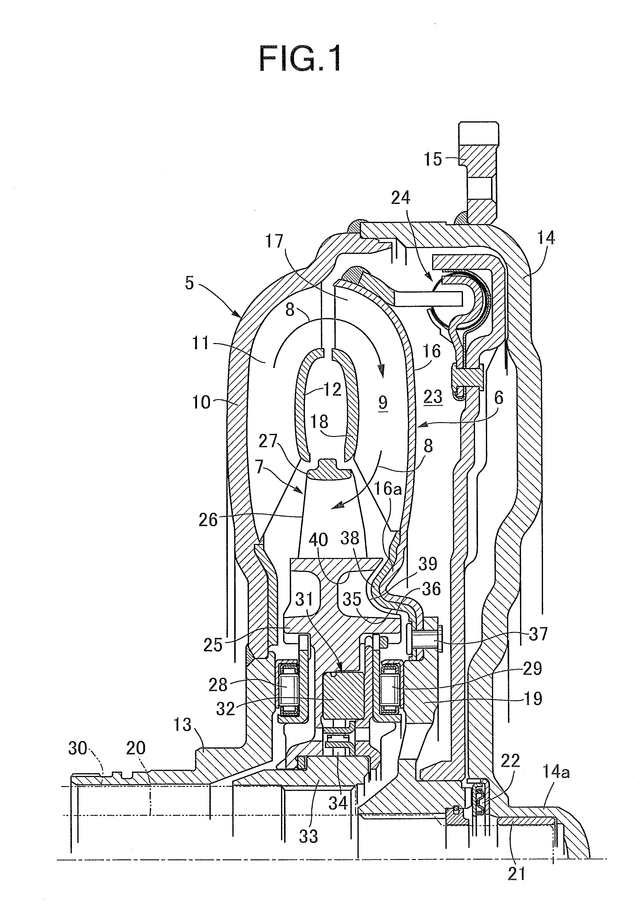
[0019]Explaining an embodiment of the present invention with reference to accompanying FIG. 1 hereinafter, a torque converter includes a pump impeller 5, a turbine runner 6 that is disposed to face the pump impeller 5, and a stator 7 that is disposed between inner peripheral portions of the pump impeller 5 and the turbine runner 6, and among the pump impeller 5, the turbine runner 6 and the stator 7, a circulation circuit 9 that circulates a hydraulic oil is formed as shown by arrows 8.

[0020]The pump impeller 5 has a bowl-shaped pump shell 10, a plurality of pump blades 11 that are provided on an inner surface of the pump shell 10, a pump core ring 12 that connects the pump blades 11, and a pump hub 13 that is fixed to an inner peripheral portion of the pump shell 10 by welding, for example, and an oil pump (not illustrated) that supplies the hydraulic oil to the torque converter is operatively connected to the pump hub 13.

[0021]Further, a side cover 14 which covers the turbine runn...


PUM


Abstract

In a torque convertor including a pump impeller, a turbine runner and a stator, an outer regulation surface facing inwards in a radial direction is provided at a turbine shell on an inward side in the radial direction from a turbine blade, an inner regulation surface that approaches and faces the outer regulation surface from inside in the radial direction is provided at a stator hub, and at least one of the outer regulation surface and the inner regulation surface is formed into a ring shape. Accordingly, movement of the stator along the radial direction at a time of transportation is inhibited and it is made unnecessary to form flange portions at core rings of the pump impeller and the turbine runner.

Description

CROSS REFERENCE TO RELATED APPLICATIONS[0001]The present application claims priority under 35 U.S.C. §119 to Japanese Patent Application No. 2014-119598 filed Jun. 10, 2014 the entire contents of which are hereby incorporated by reference.BACKGROUND OF THE INVENTION[0002]1. Field of the Invention[0003]The present invention relates to a torque converter comprising: a pump impeller in which a plurality of pump blades are provided on an inner surface of a pump shell having an inner peripheral portion fixedly provided at a pump hub; a turbine runner in which a plurality of turbine blades are provided on an inner surface of a turbine shell having an inner peripheral portion fixedly provided at a turbine hub that is disposed at a space in an axial direction from the pump hub; and a stator in which a plurality of stator blades are provided at an outer periphery of a stator hub and thrust bearings are respectively interposed between the pump hub and the stator hub and between the turbine hu...

Claims


Application Information

Patent Timeline
IPC IPC(8): F16H41/04F16H41/24
CPCF16H41/24F16H41/04F16H45/02
Inventor NOZAWA, YOICHISUGIMURA, YOSHIHISAOKAMOTO, HIROSHI
Owner YUTAKA GIKEN CO LTD
Why Eureka
Try Eureka