Method for Temporal Dispersion Correction for Seismic Simulation, RTM and FWI

a technology of temporal dispersion correction and seismic simulation, applied in seismology for waterlogging, instruments, measurement devices, etc., can solve the problems of finite-order approximation suffering from some degree of temporal dispersion, degrade the value of petroleum exploration and geophysical prospecting products, and temporal dispersion artifacts

Active Publication Date: 2015-12-10
EXXONMOBIL UPSTREAM RES CO
View PDF4 Cites 12 Cited by
  • Summary
  • Abstract
  • Description
  • Claims
  • Application Information

AI Technical Summary

Problems solved by technology

Using 2nd order time stepping provides a result with temporal dispersion artifacts.
But any finite-order approximation suffers from some degree of temporal dispersion.
If the temporal dispersion is not corrected, the application of this type of simu...

Method used


Image

  • Method for Temporal Dispersion Correction for Seismic Simulation, RTM and FWI
  • Method for Temporal Dispersion Correction for Seismic Simulation, RTM and FWI
  • Method for Temporal Dispersion Correction for Seismic Simulation, RTM and FWI

Examples


Embodiment Construction

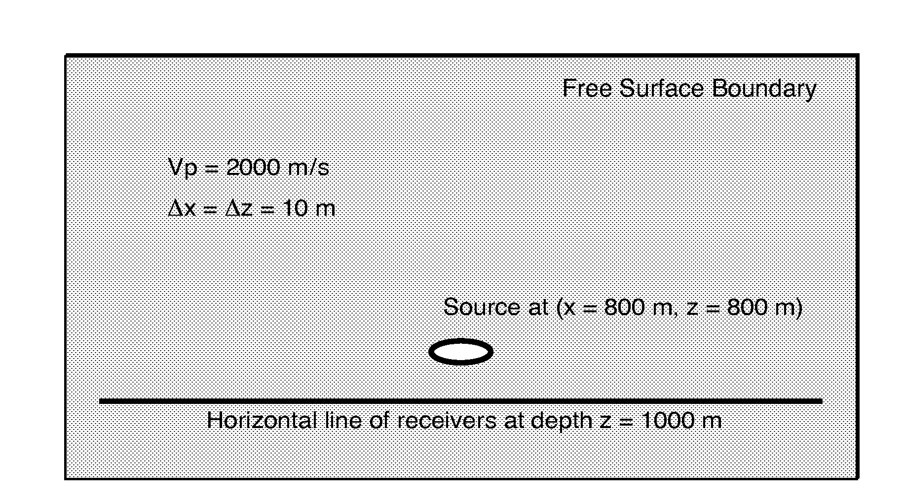
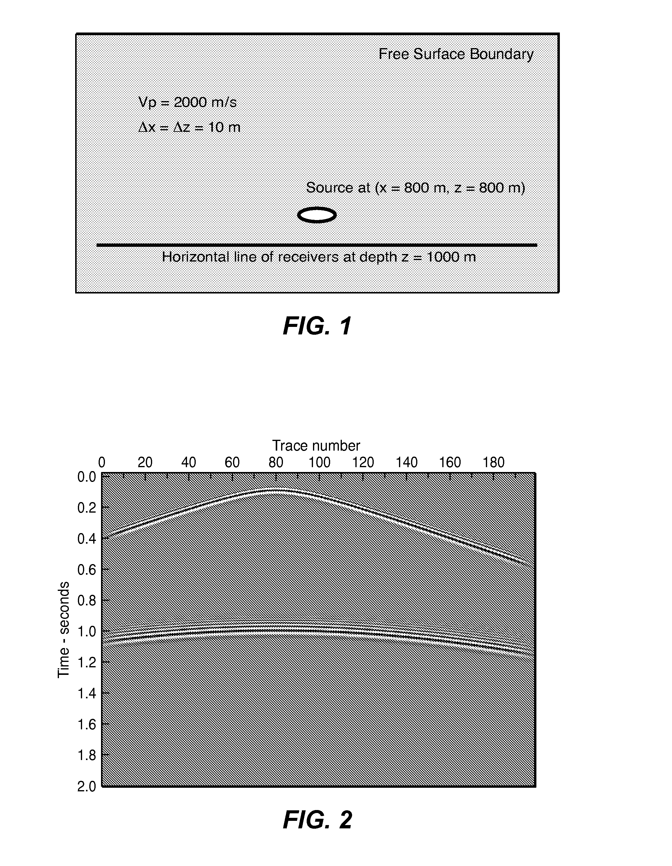
[0020]To illustrate the problem that the present invention solves, consider an earth model consisting of a simple two-dimensional half-space with a free surface boundary on top as shown in FIG. 1. The p-wave velocity is 2000 m / s. The source is located at x=800 m and z=800 m. The receivers are located on a line at a depth of 1000 m. The only reflector in the model is the free surface boundary. An impulsive source is simulated at zero time and the simulated receiver data due to a finite difference algorithm is shown in FIG. 2. The acoustic finite difference algorithm applied to the model is second order in time and 14th order in space. The vertical axis is time in seconds. The horizontal axis is trace number and there is a 10 m increment between trace locations. A large time step is used in the simulation and the events are distorted by temporal numerical dispersion. High-frequency energy arrives early. Very low-frequency energy arrives at roughly the correct time. The different wave ...


PUM


Abstract

Method for correcting seismic simulations, RTM, and FWI for temporal dispersion due to temporal finite difference methods in which time derivatives are approximated to a specified order of approximation. Computer-simulated seismic data (51) are transformed from time domain to frequency domain (52), and then resampled using a mapping relationship that maps, in the frequency domain, to a frequency at which the time derivative exhibits no temporal dispersion (53), or to a frequency at which the time derivative exhibits a specified different order of temporal dispersion. Alternatively, measured seismic data from a field survey (61) may have temporal dispersion of a given order introduced, by a similar technique, to match the order of approximation used to generate simulated data which are to be compared to the measured data.

Description

CROSS-REFERENCE TO RELATED APPLICATION[0001]This application claims the benefit of U.S. Provisional Patent Application 62 / 009,593, filed Jun. 9, 2014, entitled A Method for Temporal Dispersion Correction for Seismic Simulation, RTM and FWI, the entirety of which is incorporated by reference herein.FIELD OF THE INVENTION[0002]The invention relates generally to the field of geophysical prospecting for hydrocarbons and, more particularly, to seismic data processing. Specifically, the invention relates to the technical fields of seismic simulation, reverse time depth migration, and full waveform inversion of seismic data to infer a subsurface model of velocity or other physical property. In addition, many other useful industrial simulators for doing electromagnetic propagation, reservoir simulation and heat flow may match the form needed for this invention to apply. As will be explained later in the invention disclosure, the necessary form corresponds to that of a stationary differentia...

Claims


Application Information

Patent Timeline
IPC IPC(8): G01V1/32G01V1/48G01V1/36
CPCG01V1/32G01V2210/42G01V1/48G01V1/36G01V1/28G01V2210/44G01V2210/51G01V2210/679
Inventor ANDERSON, JOHN E.BAUMSTEIN, ANATOLYMARCINKOVICH, CAREYVDOVINA, TETYANABRYTIK, VALERIY
Owner EXXONMOBIL UPSTREAM RES CO
Why Eureka
Try Eureka