Substrate structure applicable to vertical light emitting element and vertical light emitting element thereof

a technology of substrate structure and light-emitting element, which is applied in the direction of basic electric elements, electrical apparatus, and semiconductor devices, can solve the problems of restricted application of pss, and achieve the effect of expanding the application

Inactive Publication Date: 2015-12-10
PHECDA TECH
View PDF4 Cites 0 Cited by
  • Summary
  • Abstract
  • Description
  • Claims
  • Application Information

AI Technical Summary

Benefits of technology

[0009]In view of the known technical problems, the purpose of the present invention is to provide a substrate structure which is applicable to apply the pattern sapphire substrate to the manufacturing process of a vertical light emitting element so as to expand the application of PSS.
[0010]According to the purpose of the present invention, it provides a substrate structure which may comprise a transparent substrate and a reflective layer, and the transparent substrate may comprise an upper surface and a lower surface, the reflective layer may be disposed on the upper or the lower surface, and the reflective layer may assist a yellow light manufacturing process in focusing.

Problems solved by technology

Using the microstructure of the pattern sapphire substrate (PSS) to increase the light extraction enhancement is the mainstream of the industry, however, while a transparent substrate is used to focus, the light source will directly penetrate therethrough which leads to an incorrect focus, resulting that the PSS is enable to be used in the manufacturing process of the vertical light emitting element, and the application of the PSS is therefore restricted.

Method used


Image

  • Substrate structure applicable to vertical light emitting element and vertical light emitting element thereof
  • Substrate structure applicable to vertical light emitting element and vertical light emitting element thereof
  • Substrate structure applicable to vertical light emitting element and vertical light emitting element thereof

Examples


Embodiment Construction

[0030]Hereinafter, embodiments of the present invention will be described in detail with reference to the accompanying drawings so that those skilled in the art to which the present invention pertains can realize the present invention. As those skilled in the art would realize, the described embodiments may be modified in various different ways, all without departing from the spirit or scope of the present invention.

[0031]The exemplary embodiments of the present invention will be understood more fully from the detailed description given below and from the accompanying drawings of various embodiments of the invention, which, however, should not be taken to limit the invention to the specific embodiments, but are for explanation and understanding only.

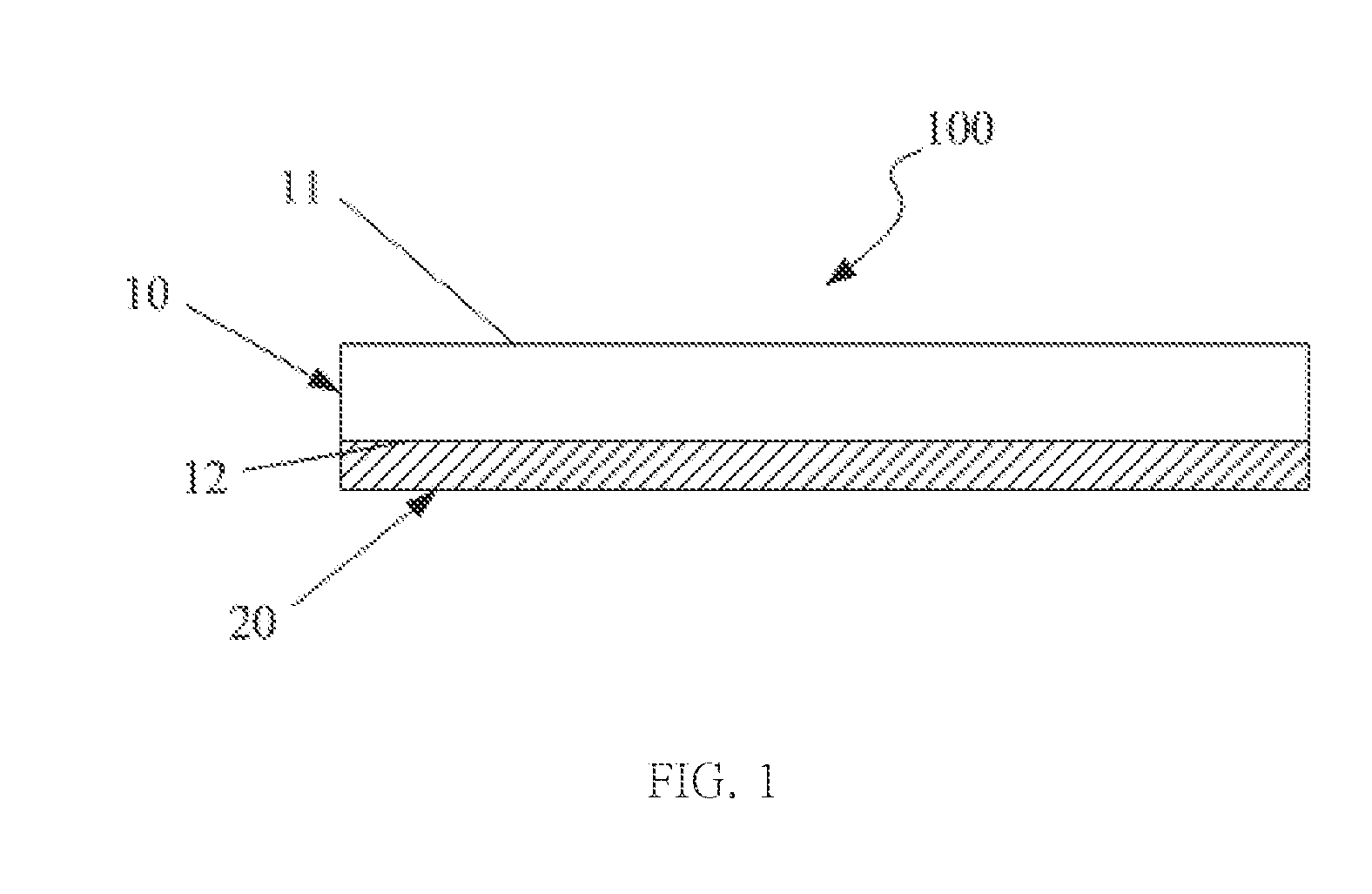
[0032]Please refer to FIG. 1 which is a schematic diagram of a substrate structure of the resent invention. As the FIG. shows, a transparent substrate 100 comprises a transparent substrate 10 and a reflective 20. The transparent substrat...


PUM


Abstract

The present invention discloses a substrate structure applicable to a vertical light emitting element and a vertical light emitting element thereof. The substrate structure comprises a transparent substrate and a reflective layer, and the reflective layer is used to improve a focus of a yellow light manufacturing process. The technique is applicable to PSS substrate and the substrate structure is used to produce the vertical light emitting element to increase the light emitting efficiency.

Description

CROSS-REFERENCE TO RELATED APPLICATION[0001]This application claims priority from Taiwan Patent Application No. 103210136, filed on Jun. 9, 2014, in the Taiwan Intellectual Property Office, the content of which are hereby incorporated by reference in their entirety for all purposes.BACKGROUND OF THE INVENTION[0002]1. Field of the Invention[0003]The present invention discloses a substrate structure, in particular with respect to a substrate structure applicable to light emitting element.[0004]2. Description of the Related Art[0005]Two electrode layers of a vertical light emitting element are respectively disposed at two sides of a light emitting layer, such that almost the currents are able to vertically flow through the light emitting layer, and only a few currents flow transversely. Therefore, it can improve the currents distribution of the plane structure so as to increase light emitting efficiency, and also resolve the shading of electrode to promote the light emitting area of LE...

Claims


Application Information

Patent Timeline
Patent Type & Authority Applications(United States)
IPC IPC(8): H01L33/60H01L33/62
CPCH01L33/62H01L33/60H01L33/46H01L33/0093
Inventor KUANG, KUANG-NINGLEE, CHI-WEICHEN, JIAN-JHIH
Owner PHECDA TECH
Why Eureka
Try Eureka