Power fluctuation detection and analysis

a power fluctuation and detection technology, applied in the field of monitoring communications systems, can solve problems such as the probability of failure of other cable modems, potentially installed at different times, and failure of individual cable modems, and achieve the effect of simplifying the identification of actual network problems and facilitating the identification of potential failure points

Active Publication Date: 2015-12-10
TIME WARNER CABLE ENTERPRISES LLC
View PDF3 Cites 239 Cited by
  • Summary
  • Abstract
  • Description
  • Claims
  • Application Information

AI Technical Summary

Benefits of technology

[0008]The network monitoring system collects transmission power level information and/or receive power level information from a plurality of customer premise devices connected to the same distribution node for each of a plurality of network distribution nodes. For an individual network distribution node, the network monitoring system calculates a set of fluctuation parameters. In at least some embodiments the set of fluctuation parameters include a group power level deviation metric, e.g., a modified standard deviation ratio, and various other group parameters, e.g., a number of fluctuating accounts, a number of fluctuating devices, a number of critical violations, a number of warning violations, a percentage of accounts that are fluctuating and a percentage of devices that are fluctuating. The network monitoring system evaluates the generated fluctuation parameters and responds, e.g., generating, outputting and/or storing fluctuations reports, modifying a data collection profile being used by a set of customer premise devices corresponding to a distribution node, commanding diagnostics to be performed on a portion of the network and/or directing a service technician. The network monitoring system compares generated fluctuation parameters corresponding to different distribution nodes, and uses the results of the comparison to assign priority with regard to the assignment of limited available troubleshooting and repair resources. The network monitoring system may, and in some embodiments does, automatically alter when power level measurements are conducted and/or request additional measurements in response to detected power level fluctuations at a distribution node thereby facilitating identification of the problem and/or problems causing the fluctuations.
[0009]By considering power fluctuating information corresponding to multiple customer premise devices, e.g., cable modems, in a region, distribution problems, e.g., particular problem distribution nodes and/or communications links which are shared by the cable modems suffering transmit and/or receive power fluctuations can be identified. Thus, actual or potential problems can be identified and/or isolated within a large network. In some embodiments in response to detecting potential problems, increased monitoring and/or monitoring at different times is automatically implemented to help identify and isolate the source of reported transmission and/or receive power fluctuations. Such power fluctuations may be caused, e.g., by temperature fluctuations at a node or shared communications link due to normal heating an

Problems solved by technology

The failure of an individual cable modem provides little information with regard to the probability that other cable modems, potentially installed at different times, are likely to fail.
Distribution nodes and/or communications links which are used in a network to supply content to multiple customer premise devices are potential network failure points which can affect a large number of customer premise

Method used


Image

  • Power fluctuation detection and analysis
  • Power fluctuation detection and analysis
  • Power fluctuation detection and analysis

Examples


Embodiment Construction

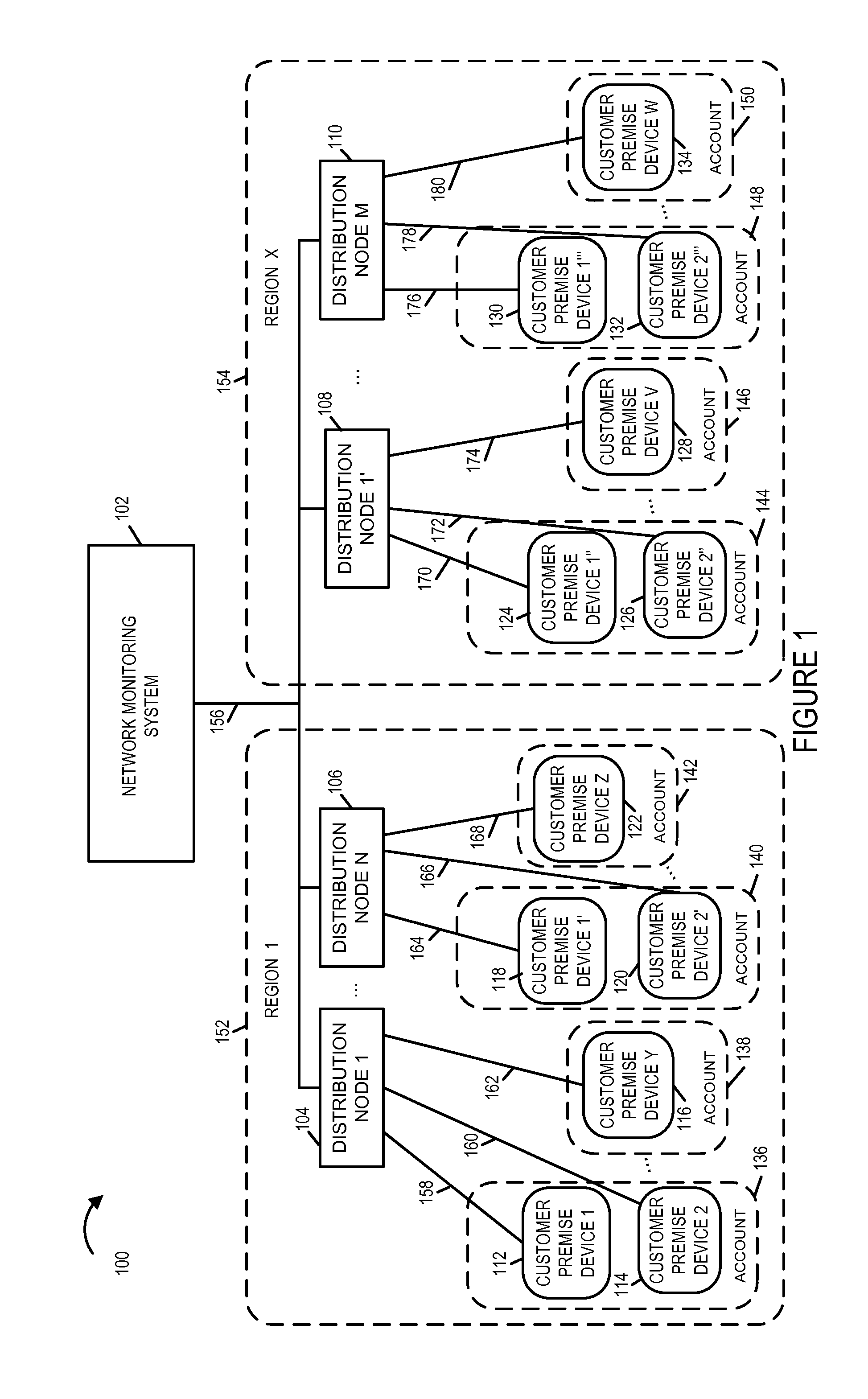
[0027]FIG. 1 is a drawing of an exemplary communications system 100, e.g., a cable network communications system, including fluctuation detection and analysis in accordance with an exemplary embodiment. Exemplary communications system 100 includes a network monitoring system 102, a plurality of distribution nodes, and a plurality of customer premise devices. In exemplary system 100 there are a plurality of regions (region 1152, . . . . , region X 154.) In region 1152, there are a plurality of distribution nodes (distribution node 1104, . . . , distribution node N 106). In region 1152, there are a plurality of customer premise devices (customer premise device 1112, customer premise device 2114, . . . , customer premise device Y 116) connected to distribution node 1104 via links (158, 160, . . . , 162), respectively. In region 1152, there are a plurality of customer premise devices (customer premise device 1′118, customer premise device 2′120, . . . , customer premise device Z 122) co...


PUM


Abstract

The network monitoring system collects transmission and/or receive power level information from a plurality of customer premise devices connected to the same distribution node for each of a plurality of network distribution nodes. For an individual network distribution node, the network monitoring system calculates a set of fluctuation parameters including a group power level deviation metric, e.g., a modified standard deviation ratio. The network monitoring system evaluates the generated fluctuation parameters and responds, e.g., outputting a fluctuations report, modifying a data collection profile being used by a set of customer premise devices corresponding to a distribution node, commanding diagnostics to be performed on a portion of the network and/or directing a service technician. The network monitoring system compares generated fluctuation parameters corresponding to different distribution nodes, and uses the results of the comparison to assign priority with regard to the assignment of limited available troubleshooting and repair resources.

Description

RELATED APPLICATIONS[0001]The present application is a continuation of pending U.S. patent application Ser. No. 13 / 468,564 filed on May 10, 2012 which claims the benefit of US Provisional Patent Application Ser. No. 61 / 641,295, titled “POWER FLUCTUATION DETECTION AND ANALYSIS” filed May 1, 2012 each of which is hereby expressly incorporated by reference in its entirety.FIELD OF INVENTION[0002]Various embodiments are directed to monitoring communications systems, e.g., cable network communications systems, and, more specifically, to detecting, analyzing and / or utilizing signal fluctuations to detect network faults and / or allocating resources for preventing network outages prior to the occurrence of a fault which may result in a network service outage.BACKGROUND[0003]Some existing systems identify a hard type failure on an individual customer premise device, e.g., a cable modem, based on an individual poll and use of simple threshold, e.g., a comparison to a pass / fail power level thre...

Claims


Application Information

Patent Timeline
IPC IPC(8): H04L12/26H04L69/40
CPCH04L43/08H04L69/40H04N17/00H04L43/045H04L41/0654H04N7/00H04L41/06H04L69/00
Inventor BERGER, WILLWYNKOOP, MARKWYMAN, MARKDEMPSEY, NOEL
Owner TIME WARNER CABLE ENTERPRISES LLC
Why Eureka
Try Eureka