

Olefin Polymerization Process With Continuous Transfer
a technology of olefin polymerization and continuous transfer, which is applied in the field of olefin polymerization process with continuous transfer, can solve the problems of settling legs, thereby not keeping constant pressure in the loop reactor, and present problems, so as to improve operability/reliability, avoid polymer stagnation, and optimize the effect of residence tim
Active Publication Date: 2015-12-17
TOTAL RES & TECH FELUY
View PDF2 Cites 5 Cited by
- Summary
- Abstract
- Description
- Claims
- Application Information
AI Technical Summary
Benefits of technology
The present invention improves the performance and reliability of a process by reducing polymer stagnation and optimizing the time it takes to settle in certain parts of the system.
Problems solved by technology
In these polymerization processes, settling legs, however, do present some problems.
Each time a settling leg reaches the stage where it “discharges” or “fires” accumulated polymer slurry it causes interferences on the pressure in the loop reactor, which is thereby not kept constant.
At very high monomer concentration, such pressure fluctuations may generate several problems such as the creation of gas bubbles that may cause trouble in the operation of the circulation pump.
They may also provoke perturbations in the control scheme of the reactor pressure.
However the above-described apparatus and processes have the disadvantage that the suspension withdrawn from the reactor still contain a large amount of diluent and of other reactants, such as the monomer, which it is then necessary to subsequently separate from the polymer particles and to treat for the purpose of reusing it in the reactor.
Another disadvantage of the above-described apparatus and processes is their lack of flexibility during the phase or reaction start-up or in response to large disruptions in the normal behavior of the reactor, like sudden interruption of one of the feed streams.
Method used
View moreImage
Smart ImageViewing Examples

Examples
examples
[0142]An ethylene-hexene copolymer has been produced in presence of a metallocene catalyst inside a double-loop reactor with various configurations of the transfer section to the second reactor. The results are summarized in the following table:
Reduction ofAverage polymerdiluent / reactants flowAverage polymersolidsto downstream reactorsolidsconcentration to(per ton of polymerReactorNumber ofSettling legsconcentration inrecoveryproduced) versusdischargesettling legsdiameterloop reactorsectionscomparative exampleContinuous——41 wt-%41 wt-%comparative exampledischargeContinuous1 (continuously6″41 wt-%51 wt-%−33%dischargeopen settling leg)Discontinuous26″41 wt-%54 wt-%−41% (comparativedischargeexample)
Login to View More PUM
| Property | Measurement | Unit |
|---|---|---|
| pressure | aaaaa | aaaaa |
| pressure | aaaaa | aaaaa |
| pressure | aaaaa | aaaaa |
Abstract
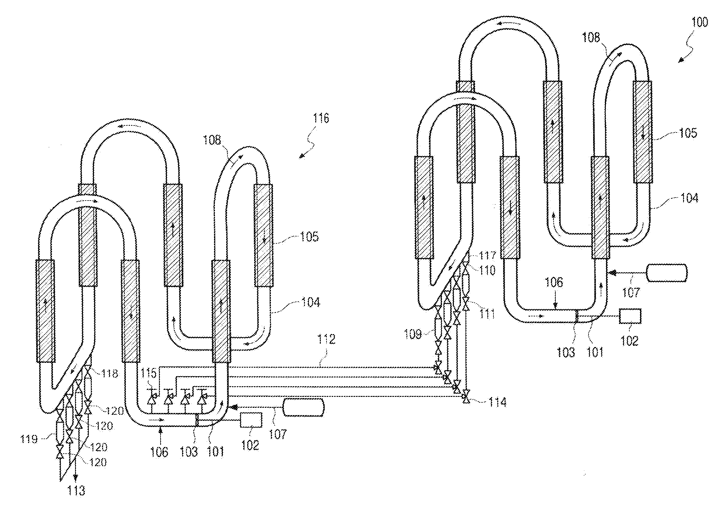
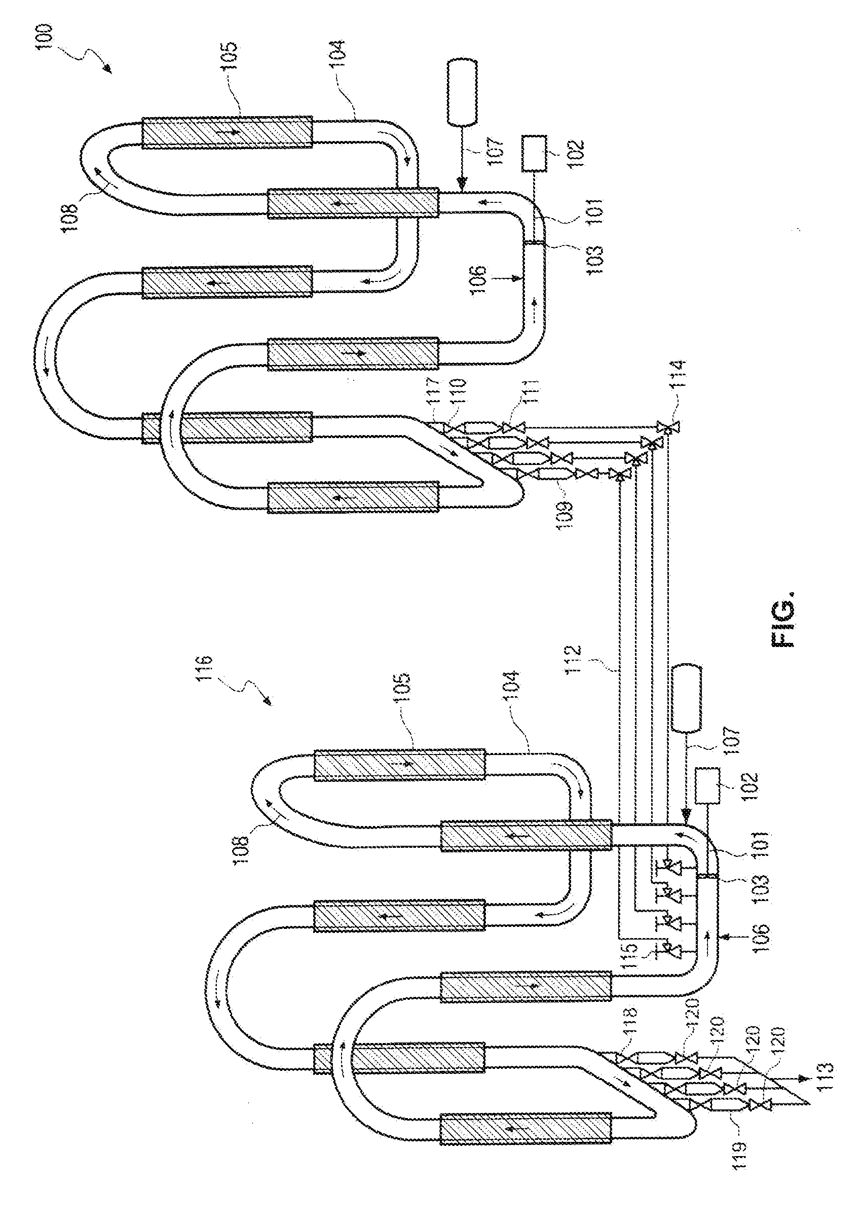
A process for the preparation of a polyolefin in at least two slurry loop reactors including a first loop reactor connected in series with a second loop reactor includes introducing olefin reactants, diluents and polymerization catalyst into the first loop reactor while circulating. The process includes polymerizing the olefin reactants to produce a polyolefin slurry, withdrawing the polyolefin slurry from the first loop reactor, and introducing withdrawn articles into the second loop reactor by means of settling legs. Each settling leg has an inlet connected to the first loop reactor and an outlet connected to the second loop reactor by means of a transfer line. At least one settling leg is continuously open allowing continuous transfer of solid olefin polymer particles from the first to the second loop reactor. The process includes controlling the continuous transfer of solid olefin polymer particles by the at least one continuously open settling leg.
Description
FIELD OF THE INVENTION[0001]The present invention relates to improvements in the removal of polymer slurry from a reactor for olefin slurry polymerization.BACKGROUND OF THE INVENTION[0002]Olefin polymerizations such as ethylene polymerization are frequently carried out using monomer, diluent and optional catalyst and optionally co-monomers in a loop reactor. The polymerization is usually performed under slurry conditions, wherein the product consists usually of solid particles and is in suspension of a diluent. The slurry contents of the reactor are circulated continuously with a pump to maintain efficient suspension of the polymer solid particles in the liquid diluent, the product being often taken off by means of settling legs which operate usually on a batch principle to recover the product. Settling in the legs is used to increase the solids concentration of the slurry finally recovered as product slurry. The product is further either transferred to another reactor or discharged...
Claims
Login to View More Application Information
Patent Timeline
 Patent Type & AuthorityApplications(United States)
IPC IPC(8): C08F2/01
CPCC08F2/01C08F2/14C08F210/16C08F210/14C08F2/001C08F10/00C08F4/65927
InventorFOUARGE, LOUISHORRE, ANNELIESNAUWELAERTS, GEERTRICHET, MARCWILDERIANE, PASCAL
OwnerTOTAL RES & TECH FELUY