An interior permanent magnet motor

a permanent magnet motor and permanent magnet technology, applied in the direction of magnetic circuit rotating parts, dynamo-electric machines, magnetic circuit shape/form/construction, etc., can solve the problems of magnet wear, cracking, magnet tend to demagnetize, etc., to reduce the movement of the magnet, improve the insertability of the magnet, and suppress the reduction of demagnetization resistance of the electric motor

Active Publication Date: 2015-12-17
MITSUBISHI ELECTRIC CORP
View PDF3 Cites 9 Cited by
  • Summary
  • Abstract
  • Description
  • Claims
  • Application Information

AI Technical Summary

Benefits of technology

[0010]According to the one embodiment of the present invention, it is possible to improve the insertability of the magnet into the magnet insertion hole and further suppressing the reduction in demagnetization resistance of the electric motor while reducing the movement of the magnet to reduce the noise and reduce the risk of wearing, cracking, and chipping of the magnet.

Problems solved by technology

A large amount of movement of the magnet inside the magnet insertion hole causes vibration and noise, which further causes wearing, cracking, and chipping of the magnet.
Therefore, there has been a problem in that, when the magnet is exposed to a magnetic field caused by a winding current of a stator, the magnet tends to demagnetize in the vicinity of the magnet stoppers of the magnet insertion hole.

Method used


Image

  • An interior permanent magnet motor
  • An interior permanent magnet motor
  • An interior permanent magnet motor

Examples


first embodiment

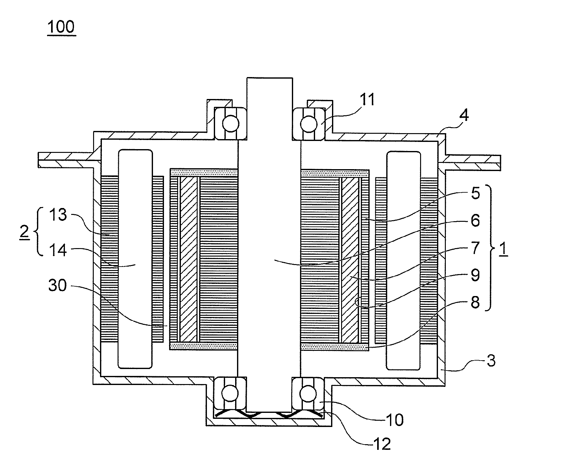
[0021]FIG. 1 is a vertical sectional view for illustrating a schematic configuration of an interior permanent magnet motor according to a first embodiment of the present invention. An interior permanent magnet motor 100 according to the first embodiment includes a rotor 1, a stator 2, a frame 3, and a bracket 4.

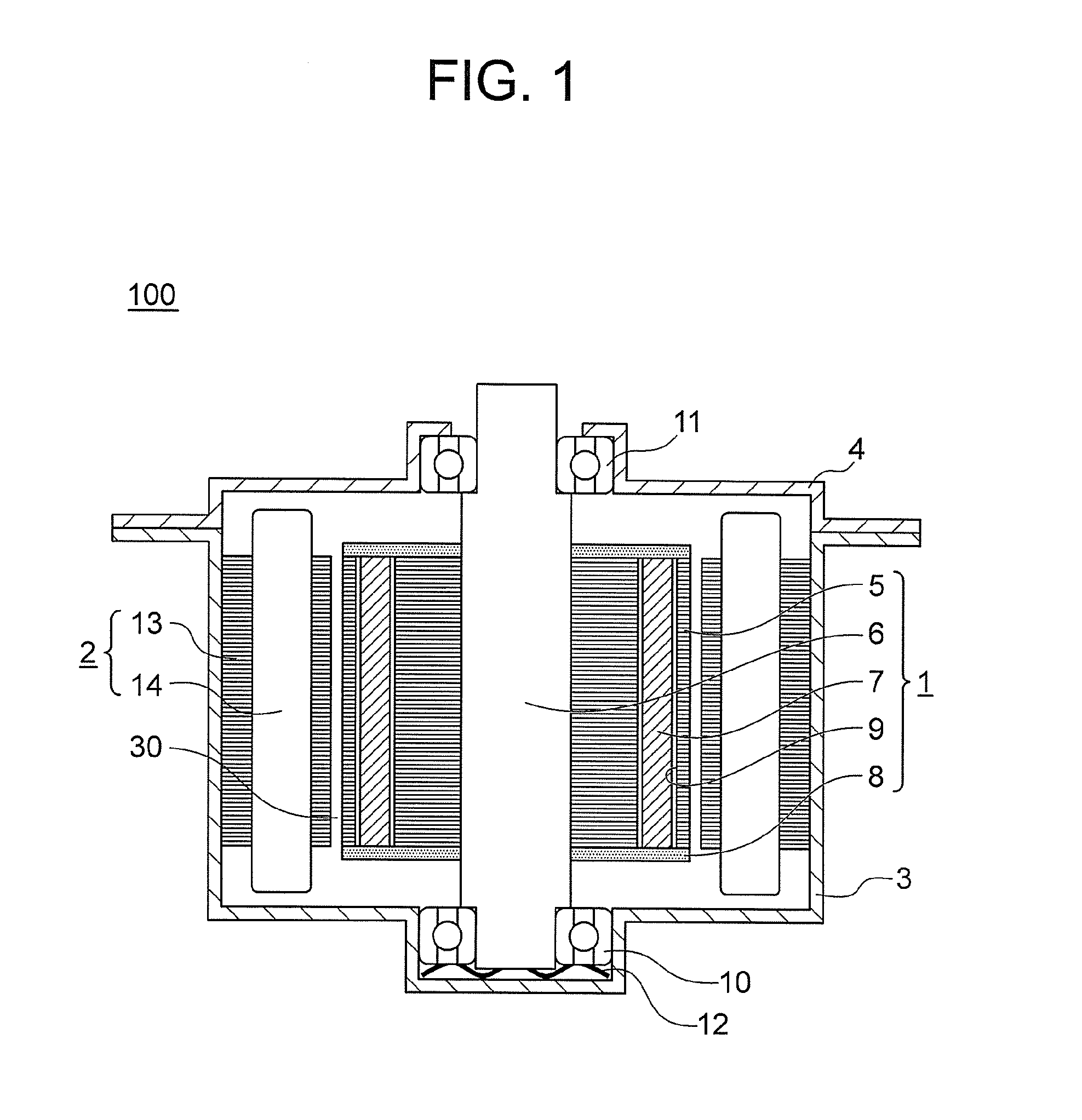
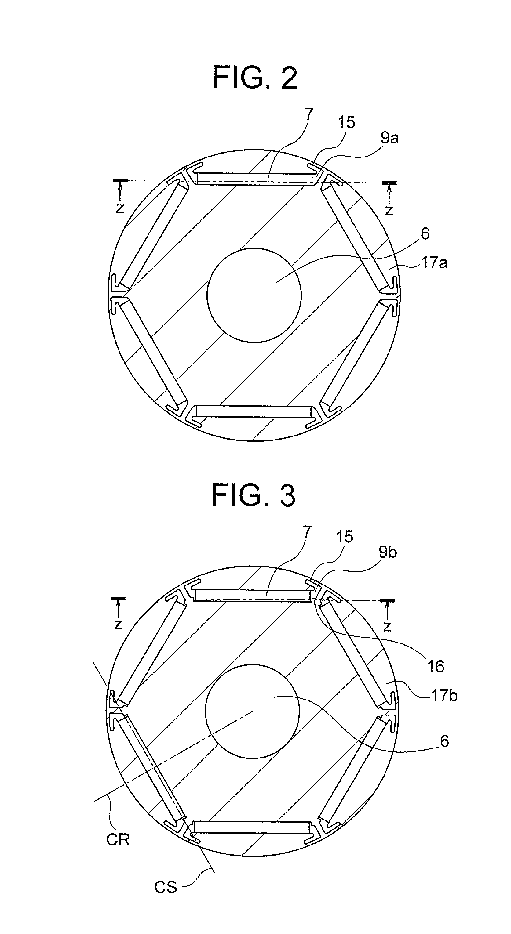
[0022]The rotor 1 includes a rotor core 5, a shaft 6, a plurality of permanent magnets (for example, rare-earth magnets) 7, and a pair of upper and lower end plates 8. The rotor core 5 is formed by, for example, laminating and fixing a plurality of magnetic steel sheets punched into a predetermined shape. The rotor core 5 has, for example, a substantially annular shape as viewed in a rotary shaft direction. The rotor core 5 has a plurality of magnet insertion holes 9 formed in parts of the outer periphery thereof. The plurality of magnet insertion holes 9 are formed as many as the number of poles, and are arranged at, for example, equal intervals in a circumferential directio...

second embodiment

[0054]Next, with reference to FIG. 6, a second embodiment of the present invention is described. FIG. 6 is a view for illustrating a relationship of abutment between a permanent magnet and a magnet stopper in an interior permanent magnet motor according to the second embodiment. Note that, the second embodiment is similar to the case of the above-mentioned first embodiment except for the part to be described below. As illustrated in FIG. 6, a chamfered portion 218 is formed at a lower corner of a permanent magnet 207.

[0055]Under a state in which the chamfered portion 218 is formed as described above, the relationship between the adjustment margin a in the circumferential direction, which is necessary for avoiding abutment of the lower corner of the permanent magnet 207 against the magnet stopper 16, and a dimension a1 of the chamfered portion 218 in the circumferential direction can be set as follows.

a1≧a  Expression (10)

When the chamfered portion 218 is formed based on Expression (...

third embodiment

[0057]Next, with reference to FIG. 7, a third embodiment of the present invention is described. FIG. 7 is a view in the same mode as FIG. 6 according to the third embodiment. Note that, the third embodiment is similar to the case of the above-mentioned first embodiment except for the part to be described below.

[0058]In the third embodiment, magnetic steel sheets 317a and 317b having the magnet insertion holes 9 formed by punching are used. That is, in punching, an upper side of a magnet stopper 316 of the magnetic steel sheet 317b becomes the shear droop side, and a lower side of the magnet stopper 316 becomes the burr side. In the third embodiment, a shear droop-shaped portion 319 generated at this time on the upper side of the magnet stopper 316 is used. Note that, in the illustrated example, a case where the magnet insertion holes 9 are formed by punching in both of the magnetic steel sheet 317a and the magnetic steel sheet 317b is illustrated, but in the fourth embodiment, such ...


PUM


Abstract

An interior permanent magnet motor includes: a rotor; a stator; and a plurality of permanent magnets respectively inserted into a plurality of magnet insertion holes formed in a rotor core, the rotor core being formed by laminating a plurality of magnetic steel sheets, the magnetic steel sheets including first magnetic steel sheets each not having a magnet stopper in the magnet insertion hole, and second magnetic steel sheets each having magnet stoppers at both end portions of the magnet insertion hole, the rotor core including a laminate of the magnetic steel sheets in a lamination mode in which, when Hn represents a distance between an upper end surface of the second magnetic steel sheet and an upper end surface of the n-th second magnetic steel sheet, a progression of differences of Hn is a geometric progression.

Description

TECHNICAL FIELD[0001]The present invention relates to an interior permanent magnet motor.BACKGROUND ART[0002]In a general interior permanent magnet motor, as many magnet insertion holes as the number of poles are formed in advance in an axial direction through a rotor core formed by laminating and fixing a plurality of magnetic steel sheets punched into a predetermined shape. When the rotor is assembled, permanent magnets are inserted into corresponding magnet insertion holes. When the electric motor is operated, forces caused by the change in attracting force between the magnet and a tooth leading end and by the acceleration and deceleration act on the magnet, and hence the magnet may move laterally in a circumferential direction inside the magnet insertion hole. A large amount of movement of the magnet inside the magnet insertion hole causes vibration and noise, which further causes wearing, cracking, and chipping of the magnet. Therefore, in the vicinity of the lateral ends of th...

Claims


Application Information

Patent Timeline
Patent Type & Authority Applications(United States)
IPC IPC(8): H02K1/27
CPCH02K1/2706H02K1/276H02K2213/03
Inventor OKETANI, NAOHIRONIGO, MASAHIROBABA, KAZUHIKOYABE, KOJI
Owner MITSUBISHI ELECTRIC CORP
Why Eureka
Try Eureka