Signal Transmission Device and Cooling Device

a transmission device and cooling device technology, applied in cooling/ventilation/heating modifications, lighting and heating apparatus, etc., can solve the problems of never good cooling efficiency of the heat generating elements corresponding to the downwind side fins, and achieve the effect of effectively cooling improving the heat radiating properties of the heat generating elements

Inactive Publication Date: 2015-12-17
HITACHI METALS LTD
View PDF2 Cites 0 Cited by
  • Summary
  • Abstract
  • Description
  • Claims
  • Application Information

AI Technical Summary

Benefits of technology

[0008]An object of the present invention is to provide a signal transmission device and a cooling device capable of improving the heat radiating properties of the heat generating elements provided so as to be adjacent to each other, and consequently capable of effectively cooling the heat generating elements.
[0019]According to the present invention, since the extending direction of fins of one heat sink corresponding to one heat generating element intersects with the extending direction of fins of the other heat sink corresponding to the other heat generating element, a cooling air that has passed through one heat sink is prevented from passing through the other heat sink. Thus, cooling air flow that has not been warmed can be supplied to both of the one heat sink and the other heat sink. Therefore, each heat radiating property of the one heat generating element and the other heat generating element provided so as to be adjacent to each other is improved, and besides, both of the heat generating elements can be efficiently cooled.

Problems solved by technology

Therefore, the cooling air passing through the downwind side fins is warm, and therefore, the cooling efficiency of the heat generating elements corresponding to the downwind side fins is never good.

Method used


Image

  • Signal Transmission Device and Cooling Device
  • Signal Transmission Device and Cooling Device
  • Signal Transmission Device and Cooling Device

Examples


Embodiment Construction

[0033]Hereinafter, one embodiment of the present invention will be explained in detail by using the drawings.

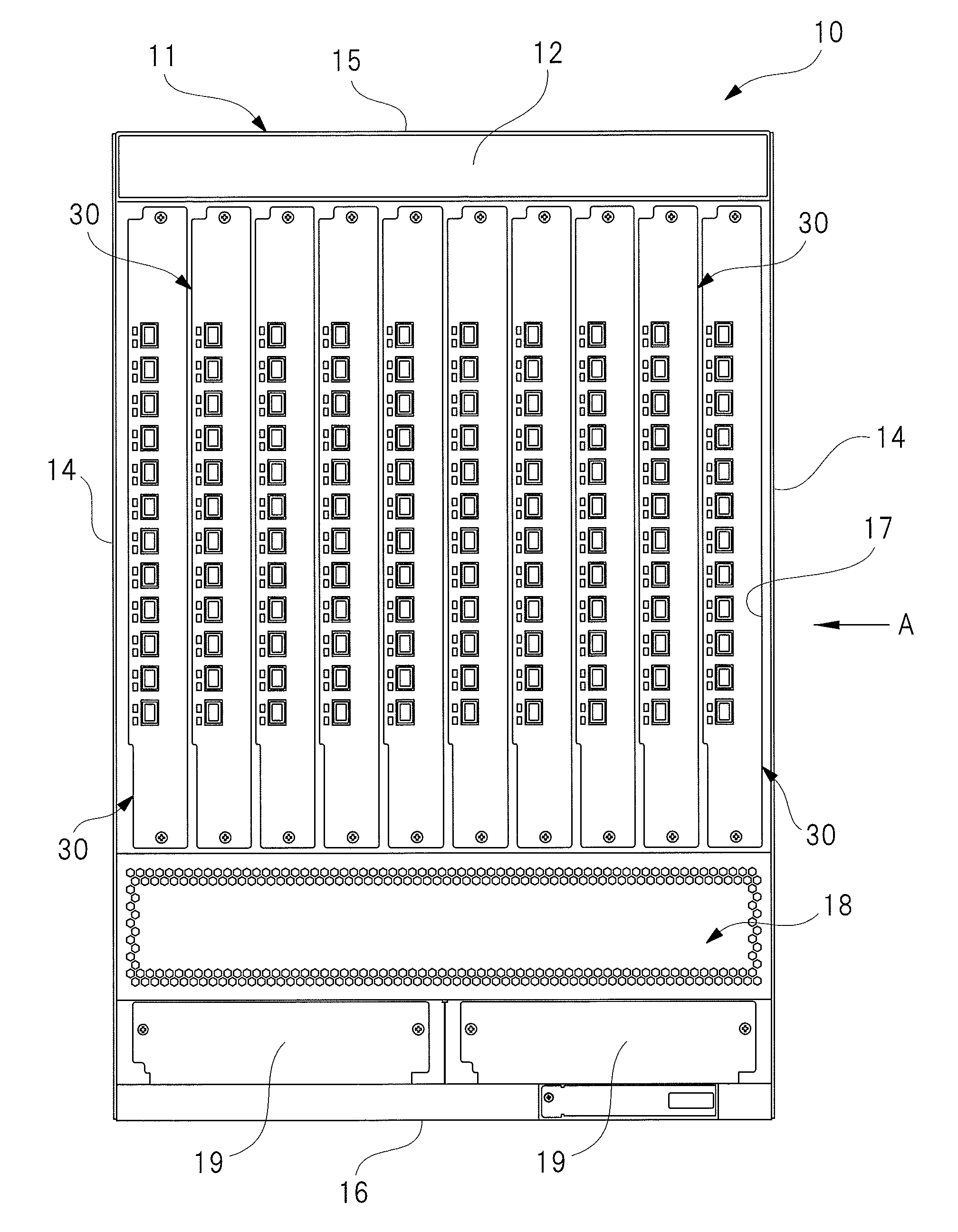
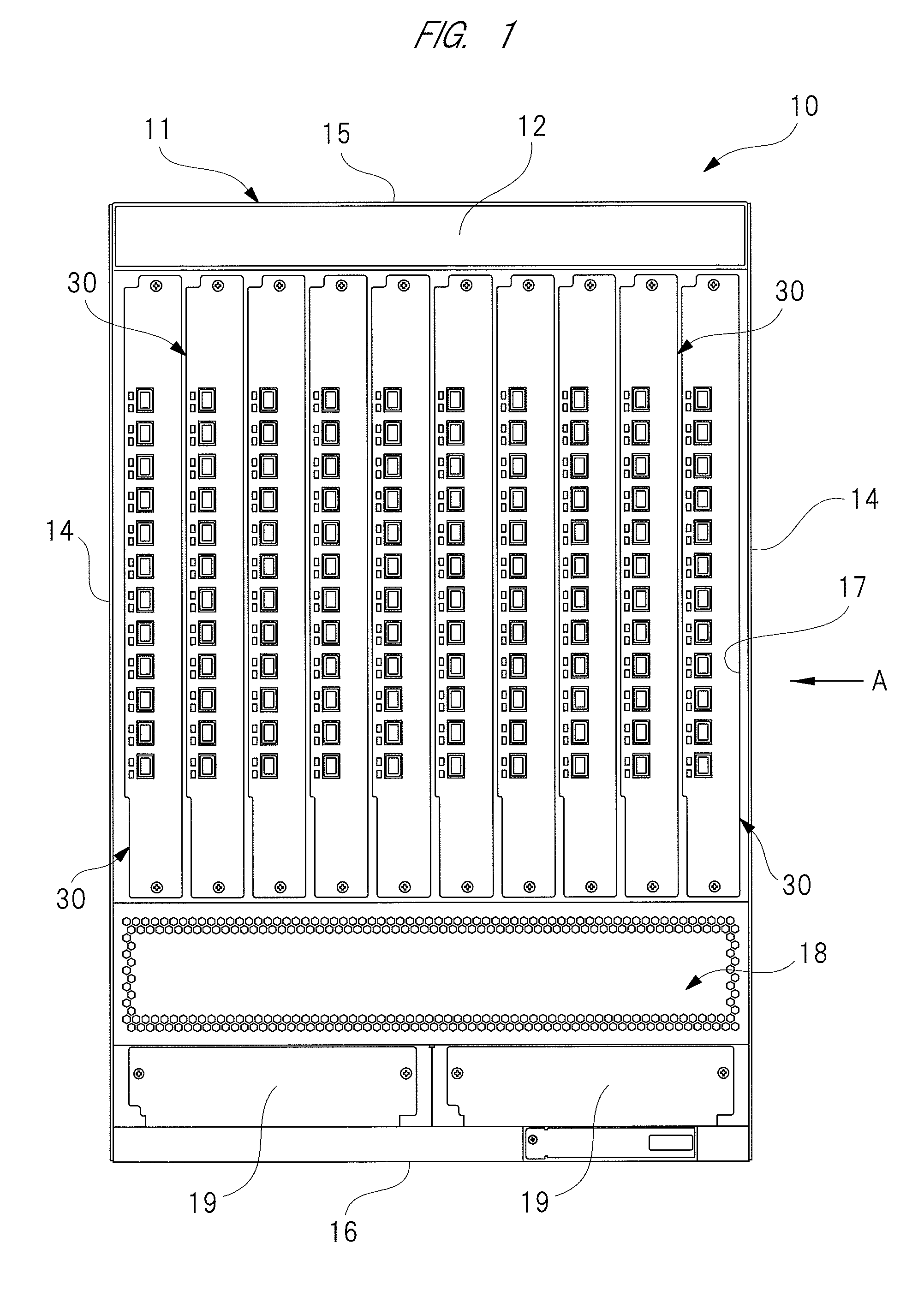
[0034]FIG. 1 is a front view showing an Ethernet switch of the present invention, FIG. 2 is a back view showing the Ethernet switch of the present invention, FIG. 3 is a view with an arrow A of FIG. 1 for explaining a flow of a cooling air inside a casing, and FIG. 4 is a plan view showing line cards housed inside the casing in detail.

[0035]As shown in FIGS. 1 to 3, an Ethernet switch 10 houses total of ten line cards 30, and controls these line cards 30 so as to be in cooperation with each other. The Ethernet switch 10 is provided with a casing 11 formed into a substantially rectangular parallelepiped shape, and the casing 11 is provided with a front wall 12, a back wall 13, a pair of side walls 14, a top wall 15 and a bottom wall 16.

[0036]As shown in FIG. 1, an insertion opening section 17 for use in housing the line cards 30 into the casing 11 is formed on the front wall 1...


PUM


Abstract

The heat generating elements are more effectively cooled by improving a heat radiating property of the heat generating elements provided so as to be adjacent to each other. An extending direction of fins of a second heat sink corresponding to a second communication-use LSI is made to intersect with an extending direction of fines of a third heat sink corresponding to a third communication-use LSI. Thus, a cooling air that has passed through the second heat sink is prevented from passing through the third heat sink. Therefore, a cooling air that is not warmed can be supplied to both of the second heat sink and the third heat sink. Thus, each heat radiating property of the second and third communication-use LSIs provided so as to be adjacent to each other can be improved. As a result, both of the second and third communication-use LSIs can be efficiently cooled.

Description

CROSS-REFERENCE TO RELATED APPLICATION[0001]The present application claims priority from Japanese Patent Application No. 2014-123699 filed on Jun. 16, 2014, the content of which is hereby incorporated by reference into this application.TECHNICAL FIELD OF THE INVENTION[0002]The present invention relates to a signal transmission device provided with a heat generating element mounted on a substrate and a heat sink for cooling the heat generating element, and also relates to a cooling device provided with a signal transmission device, a casing that houses the signal transmission device and a cooling mechanism that introduces outside air into the casing and exhausts heat of the signal transmission device outside the casing.BACKGROUND OF THE INVENTION[0003]Conventionally, as one of communication methods for allowing a plurality of computers connected by the LAN (Local Area Network) to efficiently communicate with each other, an Ethernet system (Ethernet (registered trademark)) is proposed...

Claims


Application Information

Patent Timeline
Patent Type & Authority Applications(United States)
IPC IPC(8): H05K7/20
CPCH05K7/2039H05K7/20563H05K7/20727
Inventor KANTANI, AKIHITO
Owner HITACHI METALS LTD
Why Eureka
Try Eureka