Aluminum/silicon carbide composite and radiating part comprising the same

a technology of silicon carbide and composite materials, applied in the field of aluminum/silicon carbide, can solve the problems of semiconductor chip malfunction or destruction, simple increase in heat generation amount of such semiconductor chips, and failure to efficiently dissipate such heat, etc., to achieve low thermal expansion, impart plating capability, and high thermal conductivity

Active Publication Date: 2009-04-09
DENKA CO LTD
View PDF4 Cites 10 Cited by
  • Summary
  • Abstract
  • Description
  • Claims
  • Application Information

AI Technical Summary

Benefits of technology

[0019]The aluminum-silicon carbide composite of the present invention has characteristics that it has low thermal expansion and high thermal conductivity.
[0020]Further, by providing thin and uniform aluminum layers on both principal planes of a flat plate-shaped aluminum-silicon carbide composite, it becomes possible to impart plating capability and to significantly improve flatnesses of principal planes that function as heat radiation planes. For this reason, as compared with conventional method of bow forming the composite, heat radiation property after it is soldered with a ceramic circuit substrate is improved, and thus, it is suitable for a base plate for power module for mounting semiconductor chips requiring particularly high reliability.

Problems solved by technology

In recent years, along with progress of high-integration and downsizing of semiconductor chips, heat generation amount of such semiconductor chip simply increases, and efficient dissipation of such heat has become a problem to be solved.
However, in this structure, there has been a problem that when a heat load is applied to a semiconductor device, a crack of solder layer due to the difference of thermal expansion coefficient between the base plate and the circuit substrate occurs, and as a result, heat radiation becomes insufficient to cause malfunction or destruction of a semiconductor chip.
However, if many fine irregularities are present on the base plate, a gap is formed between the base plate and the heat-dissipation fin, and even if a heat-dissipation grease having high thermal conductivity is applied, thermal conductivity is significantly decreased.
As a result, there has been a problem that heat radiation property of entire module constituted by the ceramic circuit substrate, the base plate and the heat-dissipation fin, etc. is significantly decreased.
However, when the base plate surface is wavy, there has been a problem that the bow shape and its quality are not consistent.
Further, due to the variation of bow shape or surface irregularities, there has been a problem that a large gap is still formed between the base plate and the heat-dissipation fin.
However, in this method, since the aluminum-silicon carbide composite is extremely hard, significant amount of grinding by a tool such as a diamond is required, and there has been a problem that its cost is high.
However, in a case of producing a base plate by using this method, the thickness of each surface of aluminum alloy layer after the machining of the base plate is thick.
Further, in this method, since it is necessary to control the thickness of the aluminum alloy layer on each primary plane to have uniform thickness and not to make the aluminum-silicon carbide composite exposed to the outside, there has been a problem that high degree of fabrication technique is required.

Method used


Image

  • Aluminum/silicon carbide composite and radiating part comprising the same
  • Aluminum/silicon carbide composite and radiating part comprising the same
  • Aluminum/silicon carbide composite and radiating part comprising the same

Examples


example 2

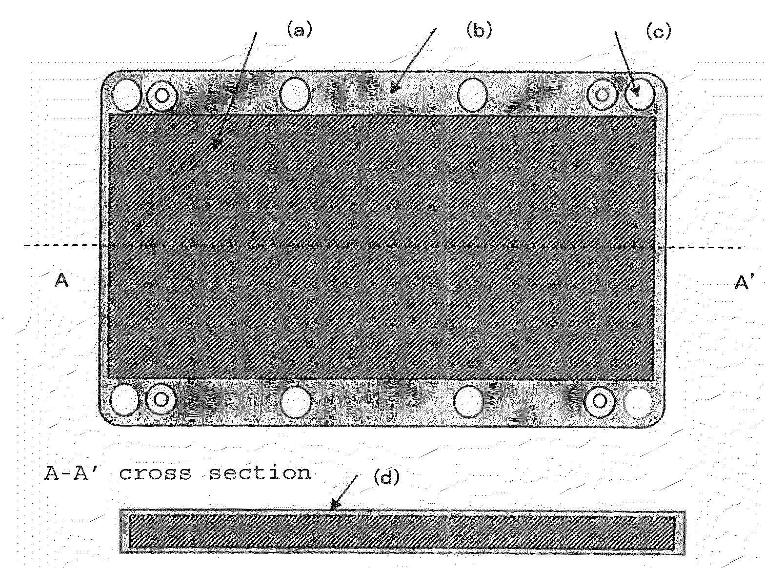
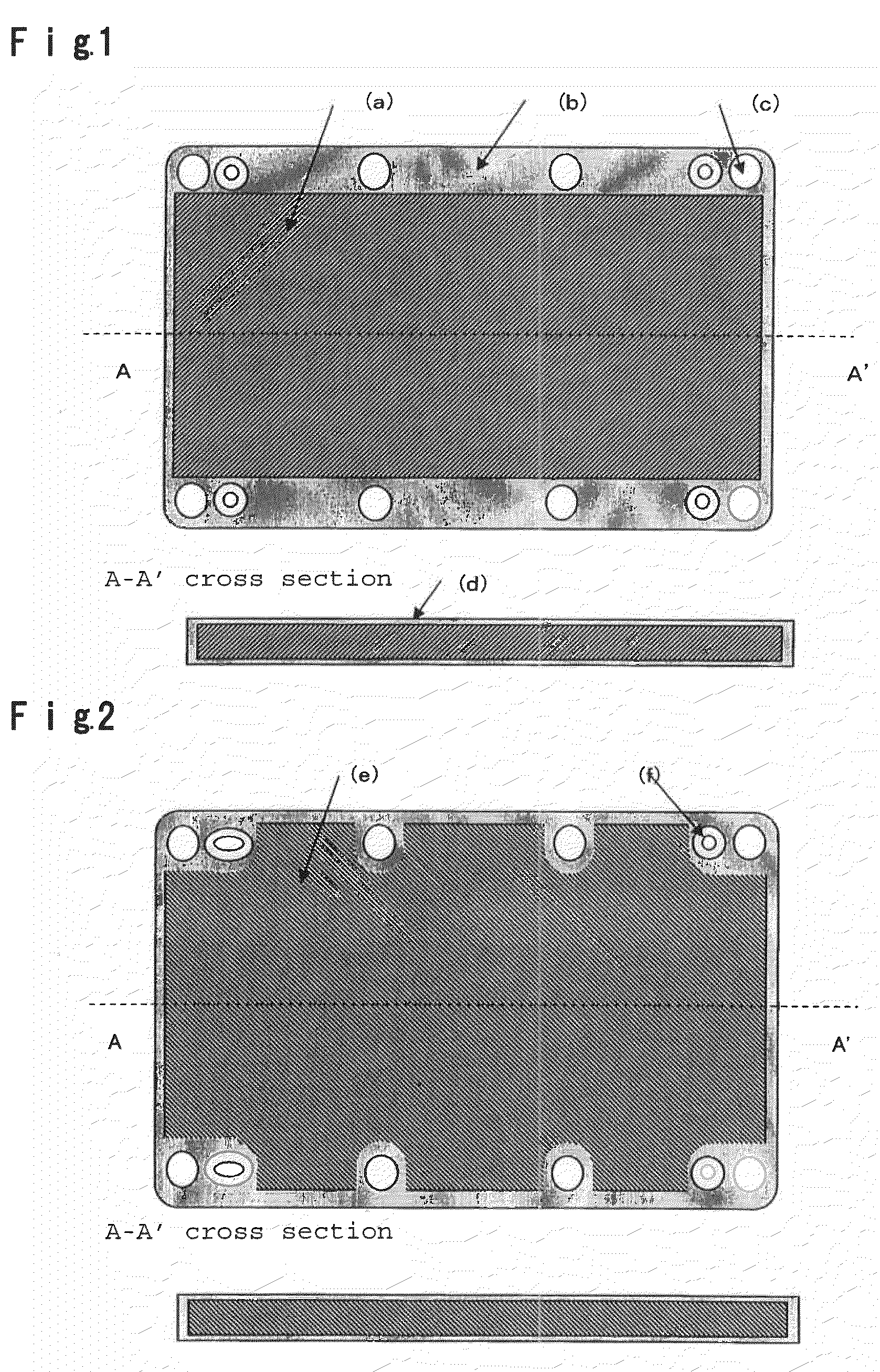
[0075]A SiC preform having a relative density of 66% was obtained in the same manner as Example 1 except that 150 g of silicon carbide particles A (manufactured by Pacific Rundum Co., Ltd.: NG-150, average particle size: 100 μm), 50 g of silicon carbide particles D (manufactured by Pacific Rundum Co., Ltd.: NG-500, average particle size: 30 μm), 100 g of silicon carbide particles C (manufactured by Yakushima Denko Co., Ltd.: GC-1000F, average particle size: 10 μm) and 30 g of silica sol (manufactured by Nissan Chemical Industries, Ltd.: Snowtex) were used as raw materials. A surface of the SiC preform obtained was ground by a surface grinding machine by using a grinding stone made of diamond so that the sample had a thickness of 4.9 mm, and the peripheral portion was machined to have an outer dimension of 183×133 mm and have the shape shown in FIG. 2. Table 3 shows the measurement results of the thickness of SiC preform after machining.

TABLE 3MeasurementItempointEx. 2Preform14.92thi...

example 3

[0078]A SiC preform was produced in the same manner as Example 2 except that the SiC preform was sintered in an atmospheric air at 1,100° C. for 2 hours. The three point bending strength of the preform obtained was 12 MPa. Table 5 shows the measurement results of the thicknesses of the SiC preform after machined. Then, the fastening torque was changed to 10 Nm, and an aluminum-silicon carbide composite was produced in the same manner as Example 1, it was subjected to a plating treatment in the same manner as Example 1 and evaluation was made in the same manner as Example 1. Table 6 shows the results.

TABLE 5MeasurementItempointEx. 3Preform15.01thickness25.01(mm)34.9945.0255.0065.0174.9885.0195.01Average (mm)5.00Maximum (mm)5.02Minimum (mm)4.98Thickness difference0.04(mm) *1*1: Thickness difference = the difference between maximum and minimum

TABLE 6ThermalAl layer thickness (μm)ThermalexpansionA surfaceB surfaceWarpageRecessconductivitycoefficient(concave surface)(convex surface)amoun...

example 4

[0079]An aluminum-silicon carbide composite was prepared in the same manner as Example 1 except that the shape of the SiC preform was 190×140×5.3 mm. In the composite obtained, 8 through holes of 8 mm in diameter were formed in the peripheral portion of the composite, and its circumference was machined by a abrasive jet cutter so that the dimension of the composite became 187×137 mm (corner portions were each R7 mm) (refer to FIG. 5). Then, in order to warp the aluminum-silicon carbide composite, a concave-convex mold having a spherical surface of a curvature radius R=12,000 mm made of carbon was used to warp the composite in the same manner as Example 1. Subsequently, the composite was subjected to a blast treatment under a pressure of 0.4 MPa and a feeding speed of 1.0 m / min with alumina abrasive particles, so as to be cleaned. Thereafter, the composite was subjected to electroless Ni—P and Ni—B platings, and as a result, a plating layer of 8 μm thick (Ni—P: 6 μm+Ni—B: 2 μm) was f...


PUM

PropertyMeasurementUnit
thicknessaaaaaaaaaa
thicknessesaaaaaaaaaa

Abstract

A base plate for power module, comprising an aluminum-silicon carbide composite and aluminum layers made of a metal containing aluminum as the main component formed on respective principal planes of the aluminum-silicon carbide composite, wherein the aluminum-silicon carbide composite is produced by forming or fabricating a flat plate-shaped silicon carbide porous body to have a thickness difference of at most 100 μm in the entire porous body and piling such porous bodies as they are each sandwiched between mold-releasing plates so that the fastening torque in the plane direction becomes from 1 to 20 Nm, and infiltrating a metal containing aluminum as the main component into the silicon carbide porous bodies,
wherein the aluminum layers each has an average thickness of from 10 to 150 μm, the difference between the maximum thickness and the minimum thickness of the aluminum layer in each principal plane is at most 80 μm, and the difference between average thicknesses of the aluminum layers on the respective principal planes is at most 50 μm, and wherein the shape of the silicon carbide porous body is rectangle or a rectangle from which peripheral portions encompassing holes are removed.

Description

TECHNICAL FIELD[0001]The present invention relates to an aluminum-silicon carbide composite suitable as a base plate for power module and a heat radiation component employing the same.BACKGROUND ART[0002]In recent years, along with progress of high-integration and downsizing of semiconductor chips, heat generation amount of such semiconductor chip simply increases, and efficient dissipation of such heat has become a problem to be solved. For this purpose, as a circuit substrate for power module, a circuit substrate is used, which comprises a ceramic substrate such as an aluminum nitride substrate or a silicon nitride substrate having high insulation property and high thermal conductivity, and a metal circuit made of copper or aluminum formed on the ceramic substrate.[0003]A typical heat radiation structure of conventional circuit substrate is that a base plate is soldered to a rear surface (heat radiation surface) of a circuit substrate via a metal plate such as a copper plate, and ...

Claims


Application Information

Patent Timeline
Patent Type & Authority Applications(United States)
IPC IPC(8): B32B3/26
CPCC04B41/009Y10T428/12479C04B41/52C04B41/88C04B41/90C04B2111/00844H01L23/13H01L23/15H01L23/3731H01L23/3733H01L23/3735C04B41/5155Y10T428/24496H01L2924/0002C22C2001/1073C22C32/0063C22C29/065C22C1/1036C04B41/4521C04B41/4523C04B41/5096C04B41/515C04B14/4631C04B41/4541C04B41/5144C04B35/565C04B38/00H01L2924/00Y10T428/24999C22C1/1073H01L23/373
Inventor HIROTSURU, HIDEKIIWAMOTO, GOHTSUKAMOTO, HIDEOHIGUMA, SATOSHIHASHIMOTO, NOBUYUKI
Owner DENKA CO LTD
Why Eureka
Try Eureka