Optical component that includes a material having a thermal longitudinal expansion with a zero crossing

a technology of optical components and thermal longitudinal expansion, applied in the field of optical components, can solve the problems of active removal of heat introduced into optical components, and the risk of failure of additional components

Active Publication Date: 2005-09-22
CARL ZEISS SMT GMBH
View PDF11 Cites 38 Cited by
  • Summary
  • Abstract
  • Description
  • Claims
  • Application Information

AI Technical Summary

Benefits of technology

[0014] It is an object of the present invention to overcome the disadvantages of the state of the art, especially to provide a possibility with which aberrations caused by the heating of the respective optical component are minimized. This goal is to be achieved with the lowest possible technical input.
[0021] Substrate materials with such a temperature-dependent coefficient of thermal expansion are for example glass ceramic materials or Ti-doped quartz glasses. Glass ceramic materials or Ti-doped quartz glass as substrate material have the advantage that layer systems without an amorphous intermediate layer can be applied on this substrate material in contrast to metallic substrate materials. A further advantage of such substrate materials is the low thermal expansion.
[0029] As a result of the roughness values of the glass ceramic materials or the TiO2-doped glass, a layer system can be structured directly on the surface of such a glass or such a glass ceramic material, which system comprises a plurality of layers which form a multiple-layer system for a normal-incidence mirror. It is similarly possible to apply a coating for a grazing-incidence EUV mirror on a glass ceramic material or a glass as a substrate material. An intermediate layer which is applied between the substrate material and the coating as described in EP 0955565 for achieving the optical surface quality is not necessary.

Problems solved by technology

A disadvantageous aspect in the solution according to EP 0 955 565 is that the minimization of aberrations introduced by the heat occurs in such away that the heat introduced into the optical component is removed actively by the cooling device.
Moreover, additional components always bear a risk for failure.
A further disadvantage in the use of metals as substrate material is that it is necessary, in order to achieve the smoothest possible surface, to coat the metal substrate with a thin film of an amorphous substance as an intermediate layer.

Method used


Image

  • Optical component that includes a material having a thermal longitudinal expansion with a zero crossing
  • Optical component that includes a material having a thermal longitudinal expansion with a zero crossing
  • Optical component that includes a material having a thermal longitudinal expansion with a zero crossing

Examples


Embodiment Construction

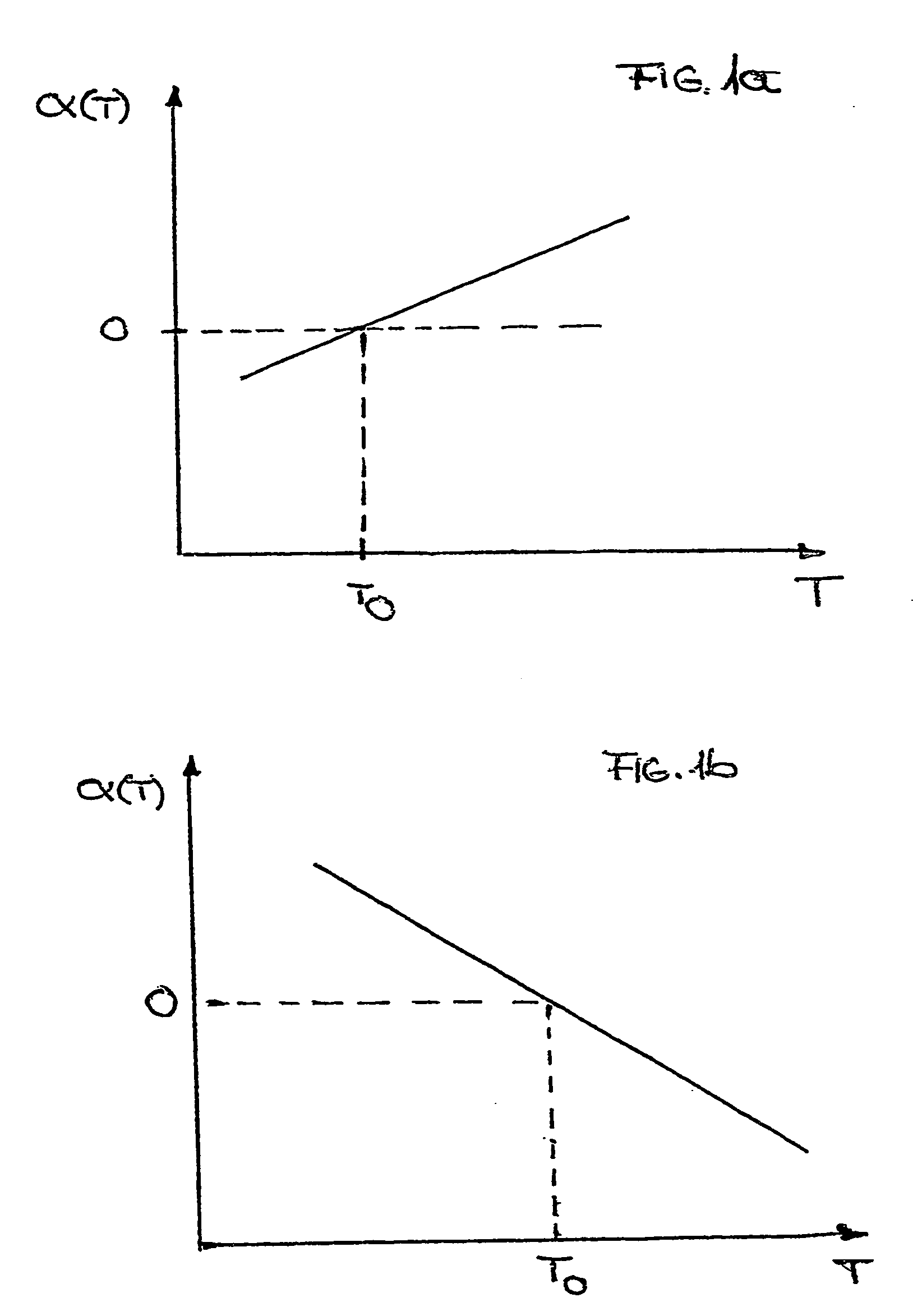
[0039] A temperature-dependent coefficient of thermal expansion of a substrate material is a temperature-dependent function α(T).

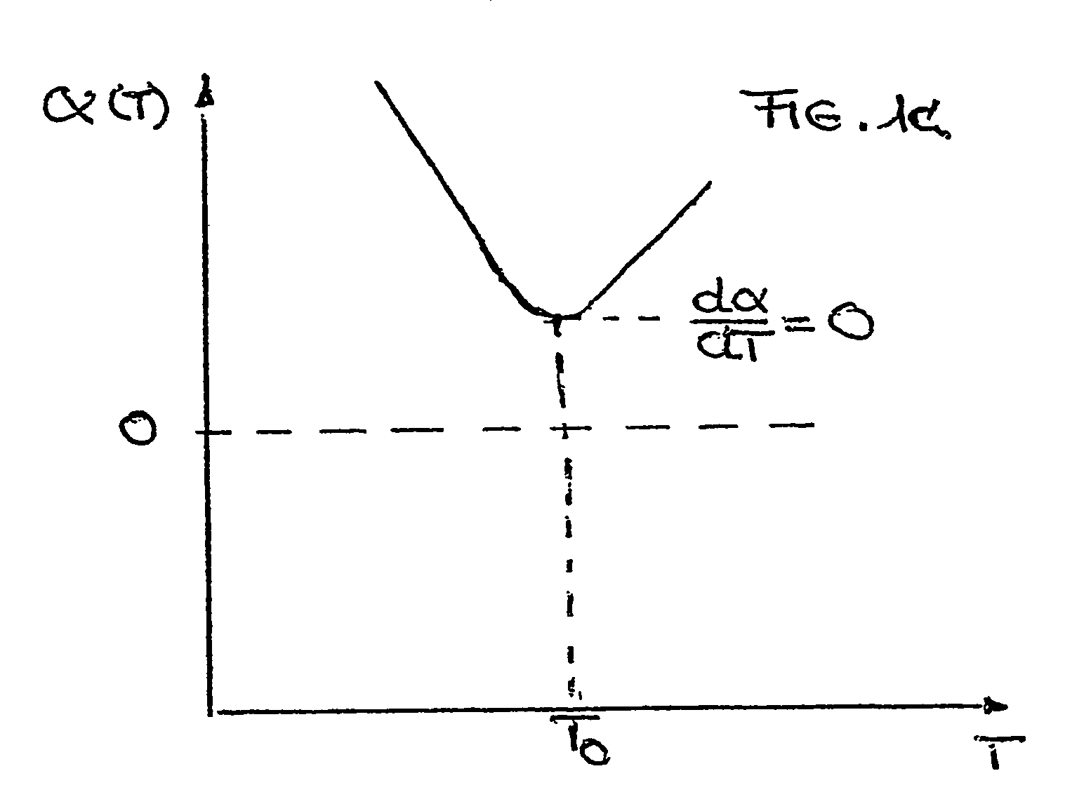
[0040] There are several possibilities for the function of α(T) for materials that are used in optical components They are shown in FIGS. 1a to 1c.

[0041]FIG. 1a is a graph of coefficient of thermal expansion α(T) as a function of temperature (T) for a TiO2-doped glass in a temperature range of approx. 20° C. to 70° C., which is of interest for EUV lithography. With a rising temperature, the temperature-dependent coefficient of thermal expansion takes on a value of zero at some point, and so, its sign changes from negative to positive. The temperature-dependent coefficient of thermal expansion thus has a zero-crossing at a temperature T0. If the temperature T is higher than T0, then the temperature-dependent coefficient of thermal expansion is positive, that is, as temperature increases, the material expands. For temperatures T lower than T0 the temperatu...


PUM

PropertyMeasurementUnit
wavelengthaaaaaaaaaa
reflectivityaaaaaaaaaa

Abstract

There is provided an optical component. The optical component includes a material having a surface that heats to a maximum temperature (Tmax) when subjected to radiation. The material has a temperature-dependent coefficient of thermal expansion (α(T)) of about zero at a temperature T0 that is approximately equal to Tmax. The optical component is suitable for use in any of an illumination system, a projection objective or a projection exposure system, as employed, for example, for EUV microlithography.

Description

CROSS-REFERENCE TO RELATED APPLICATIONS [0001] The present application is a continuation-in-part of International Application No. PCT / EP03 / 07038, filed Jul. 2, 2603, which claims priority of German Application No. 102 33 828.0, filed Jul. 24, 2002.BACKGROUND OF THE INVENTION [0002] 1. Field of the Invention [0003] The present disclosure is directed toward an optical component such as, for example, a mirror in a projection objective. Electromagnetic radiation emitted by a light source impinges on an optical surface of the optical component, and consequently, heats the optical component to a maximum temperature Tmax. The optical component is fabricated of a material having a temperature-dependent coefficient of thermal expansion α(T). [0004] Such optical components are of particular interest especially in the field of X-ray lithography. This applies in particular for lithography with soft X-rays, namely the so-called extreme ultraviolet (EUV) lithography in the wavelength region of 10...

Claims


Application Information

Patent Timeline
Patent Type & Authority Applications(United States)
IPC IPC(8): G02B1/00G02B7/18G03F7/20
CPCG02B1/00G03F7/70891G03F7/70216G02B7/181
Inventor LAUFER, TIMOFEHR, JEAN-NOELKIRCHNER, HARALDOCHSE, ANDREAS
Owner CARL ZEISS SMT GMBH
Why Eureka
Try Eureka