Use of a reticle absorber material in reducing aberrations

a technology of aberration reduction and absorber material, which is applied in the field of lithographic apparatus, can solve the problems of aberration in the wave front caused by the change in the phase of the diffraction order of the euv radiation, and achieve the effect of improving imaging by eliminating or at least minimising

Inactive Publication Date: 2005-10-06
ASML NETHERLANDS BV
View PDF6 Cites 16 Cited by
  • Summary
  • Abstract
  • Description
  • Claims
  • Application Information

AI Technical Summary

Benefits of technology

[0013] According to an aspect of the present invention there is provided a lithographic apparatus including, an illumination system for providing a projection beam of radiation, a support structure for supporting a patterning reticle, the patterning reticle serving to impart a pattern to the projection beam to form a patterned beam, a substrate table for

Problems solved by technology

Reticles currently in use result in a change in the phase of the diffraction orde

Method used


Image

  • Use of a reticle absorber material in reducing aberrations
  • Use of a reticle absorber material in reducing aberrations
  • Use of a reticle absorber material in reducing aberrations

Examples


Embodiment Construction

[0054] While specific embodiments of the invention have been described above, it will be appreciated that the invention may be practiced otherwise than as described. The description is not intended to limit the invention.

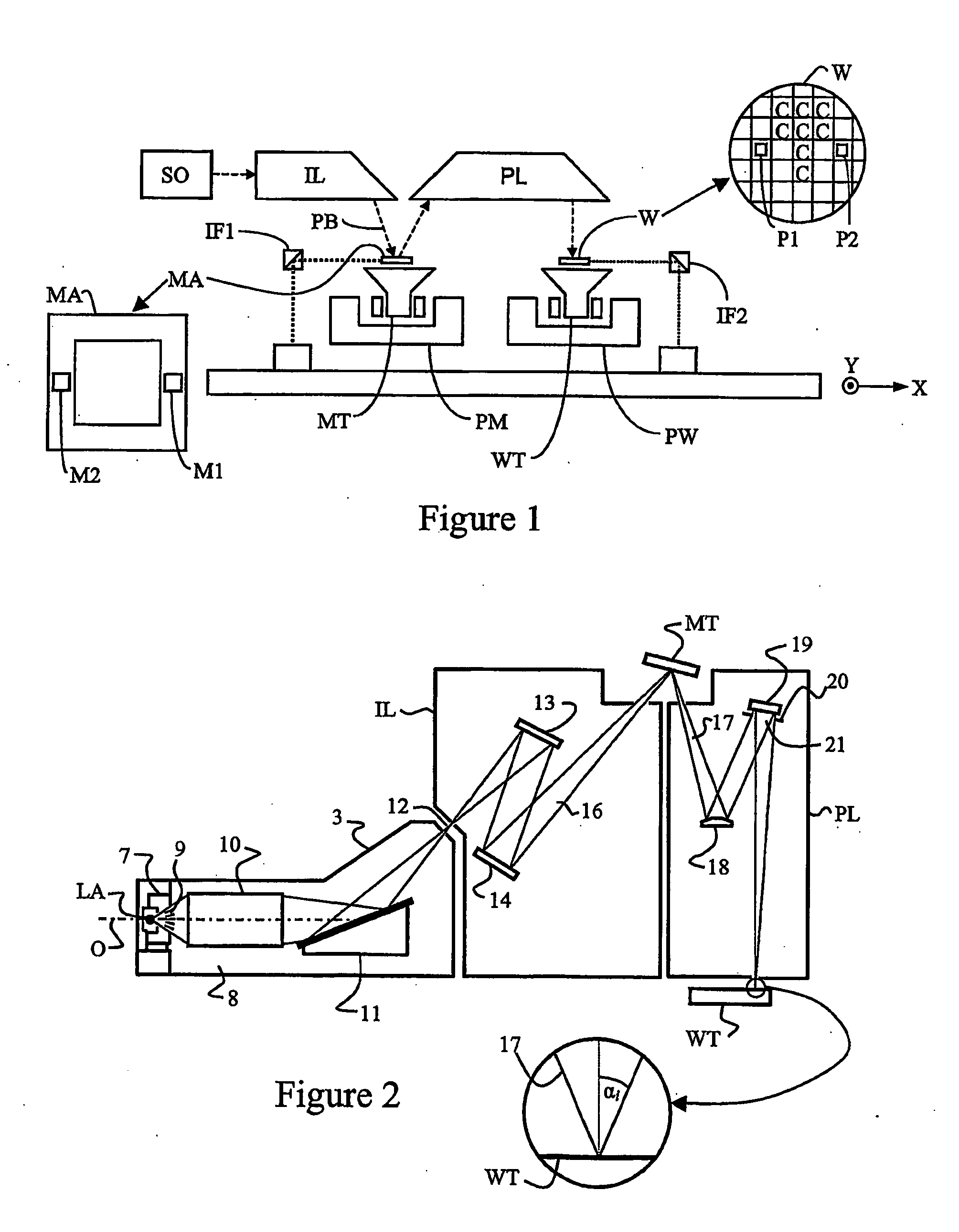
[0055]FIG. 1 schematically depicts a typical lithographic apparatus. The apparatus includes: [0056] an illumination system (illuminator) IL for providing a projection beam PB of radiation (e.g. UV or EUV radiation). [0057] a first support structure (e.g. a mask table) MT for supporting patterning structure (e.g. a mask) MA and connected to a first positioner PM for accurately positioning the patterning structure with respect to item PL; [0058] a substrate table (e.g. a wafer table) WT for holding a substrate (e.g. a resist-coated wafer) W and connected to a second positioner PW for accurately positioning the substrate with respect to item PL; and [0059] a projection system (e.g. a reflective projection lens) PL for imaging a pattern imparted to the projection beam ...


PUM


Abstract

A lithographic apparatus comprising a patterning reticle which has an aluminium absorber layer which improves imaging by eliminating or at least minimising the formation of aberrations in a patterned beam.

Description

FIELD OF INVENTION [0001] The present invention relates to a lithographic apparatus and a device manufacturing method. In particular, the present invention relates to a lithographic apparatus designed to be used with radiation having a wavelength in the Extreme Ultra-Violet (EUV) range and wherein the lithographic apparatus comprises a patterning reticle which eliminates or at least minimises the formation of aberrations in a patterned beam. BACKGROUND OF THE INVENTION [0002] A lithographic apparatus is a machine that applies a desired pattern onto a target portion of a substrate. Lithographic apparatus can be used, for example, in the manufacture of integrated circuits (ICs). In that circumstance a patterning structure, which is alternatively referred to as a mask or a reticle, may be used to generate a circuit pattern corresponding to an individual layer of the IC, and this pattern can be imaged onto a target portion (e.g. comprising part of, one or several dyes) on a substrate (e...

Claims


Application Information

Patent Timeline
IPC IPC(8): G03F7/20
CPCB82Y10/00B82Y40/00G03F1/22G03F1/24G03F7/706
Inventor DIERICHS, MARCEL MATHIJS THEODORE MARIE
Owner ASML NETHERLANDS BV
Why Eureka
Try Eureka