Wien filter

a filter and filter body technology, applied in the direction of magnetic discharge control, instruments, beam deviation/focusing by electric/magnetic means, etc., can solve the problems of adding electric and magnetic fields, adding astigmatism to imaging particle beams, adding aberrations to imaging beams, etc., to achieve the effect of compact structure and minimal derivative aberrations

Active Publication Date: 2013-05-07
ASML NETHERLANDS BV
View PDF9 Cites 14 Cited by
  • Summary
  • Abstract
  • Description
  • Claims
  • Application Information

AI Technical Summary

Benefits of technology

[0018]This invention will provide a multi-pole type Wien filter, which is especially useful for the applications in an imaging system, such as acting as monochromator or beam separator in an electron microscope. Such an application requires a strict conforming to Wien Condition to minimize derivative aberrations and a compact structure. At first, two elementary devices for a Wien filter are provided, a 12-electrode electric device and a cylindrical 4-coil magnetic device, to respectively produce an electric and a magnetic dipole fields, and each device has a compact structure. Then two designs of Wien filter constructed by using one or both of the foregoing elementary devices are proposed. In both designs, the Wien filter can generate a good match of on-axis electric and magnetic dipole fields in field distribution shape, negligibly-small 3rd order electric and magnetic field harmonics, and a desired quadrupole electric field for astigmatism compensation.

Problems solved by technology

If the Wien condition is not satisfied wherever the particles of the imaging beam will go through, the additional aberrations will be added to the imaging beam due to the undesired particle deflection.
However, fundamentally the electric and magnetic fields impossibly match each other perfectly if the electrodes in the electric deflector and the magnetic pole-pieces in the magnetic deflector are not identical in geometry.
Fundamentally, if both of the electric and magnetic dipole fields are uniform in the electric field direction, the Wien condition can not be satisfied over the entire off-axis area, thereby leading to a focusing effect in this direction and hence adding astigmatism to the imaging particle beam.
However, when a multi-pole device is excited to generate a dipole field, it actually generates a field which not only comprises a dipole field or called as 1st order harmonic but also many higher order harmonics which are undesired due to incurring aberrations.
However, due to the opening on each terminating plate for particles passing through, the electric field and magnetic field can not be terminated perfectly, and will leak out to the far fringe areas 13 and 14.
In addition, the electric field will weaken faster than the magnetic field.
For example, a longer Wien filter is not useful for an energy filter used to improve imaging resolution in SEM because of incurring a larger electron interaction; a Wien filter having larger outer radial dimensions is unaccepted for a beam separator employed to improve collection of secondary electron in SEM because its desired location is inside the bore of the magnetic objective lens.
However its requirement limits the efficiency of the Wien filter.
For this structure, it is difficult to obtain a good fields-match because the magnetic field distribution depends on the coil shape which is difficult to be made accurately.

Method used


Image

  • Wien filter
  • Wien filter
  • Wien filter

Examples


first embodiment

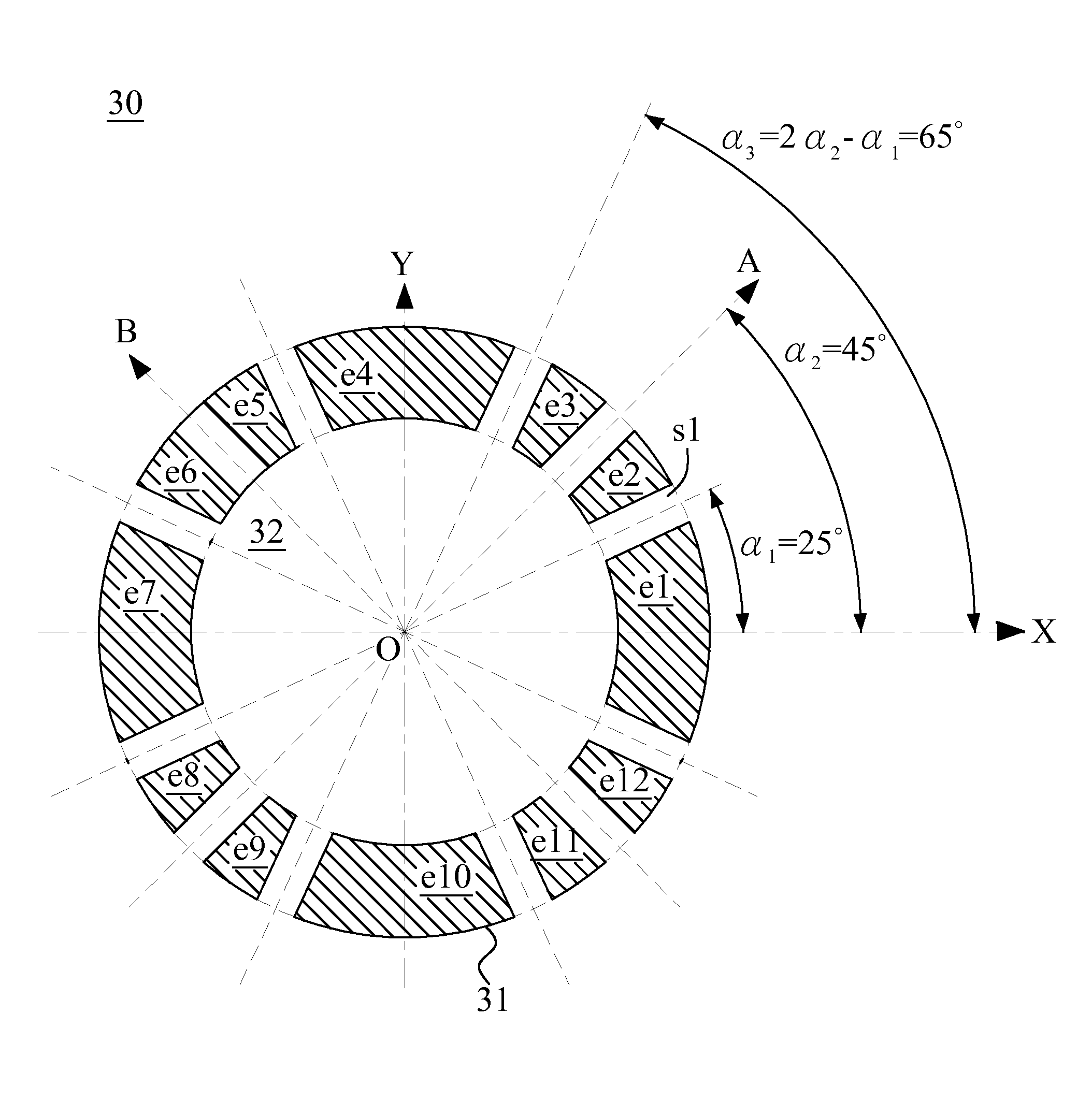
[0057]As the invention, a 12-electrode electric device 30 is proposed and shown in FIGS. 4(a)˜4(f). FIG. 4(a) is the view on a sectional plane perpendicular to the optical axis which lies on Z-axis. The electric device 30 comprises twelve electrodes e1˜e12 named in a counterclockwise rotation sequence. The electrode e1 is on the positive X-axis, and e1˜e12 are respectively named as the 1st˜12th electrodes. The twelve electrodes e1˜e12 are separated by twelve through slits s1˜s12, respectively between every two adjacent electrodes and named in the rotation sequence with respective to electrodes e1˜e12 (here only the 1st through slit s1 between the electrodes e1 and e2 is indicated for the sake of clarity). The inner ends of the twelve electrodes e1˜e12 form a cylindrical through hole 32 and an 8-fold symmetry about four planes XOZ, YOZ, AOZ and BOZ. The plane AOZ is orthogonal to the plane BOZ, and forms an angle equal to 45° with respect to the plane XOZ. The plane XOZ bisects the i...

second embodiment

[0060]As the invention, a cylindrical 4-coil magnetic device is proposed and shown in FIGS. 5(a) and 5(b). The magnetic device 40 comprises four coils c1˜c4 named in a counterclockwise rotation sequence and a cylindrical magnetic core 45 with a cylindrical through hole 46. The central axis of the through hole 46 coincides with Z-axis and is called as the central axis and optical axis of magnetic device 40. FIG. 5(a) is the view on a sectional plane perpendicular to the optical axis on Z-axis. The coils c1˜c4 are respectively winded around the inner sidewall and outer sidewall of the magnetic core 45 in 1st˜4th quadrants, and accordingly named as 1st˜4th coils. The coils c1 and c3 are bisected by the common central plane COZ and the coils c2 and c4 are bisected by the common central plane DOZ, and both of the two common central planes contain the optical axis. The coils c1˜c4 form a 4-fold symmetry about the plane XOZ and the plane YOZ. That means the plane XOZ and the plane YOZ resp...

fourth embodiment

[0063]FIGS. 7(a) and 7(b) show a Wien filter 200 as the invention. FIG. 7(a) is the view on a sectional plane perpendicular to the optical axis of the Wien filter 200. The Wien filter 200 comprises a cylindrical 12-electrode electric device same as shown in FIGS. 4(a)˜4(f) and a cylindrical 4-coil magnetic device 40 same as shown in FIGS. 5(a) and 5(b). In the electric device 30, the outline thereof is configured to be cylindrical and coaxial with the cylindrical through hole 32 thereof. In the magnetic device 40, the cylindrical through hole 46 thereof is configured to be coaxial with the cylindrical outline of the magnetic core 45. The electric device 30 is inside the cylindrical through hole 46 of the magnetic core 45 of the magnetic device 40, and the central axes of both electric device 30 and the magnetic device 40 coincide and are on Z-axis. The central axis of the electric device 30 is called as the optical axis of the Wien filter 200. The 1st electrode e1 of the electric de...


PUM


Abstract

This invention provides a multi-pole type Wien filter, which acts more purely approaching its fundamentally expected performance. A 12-electrode electric device acts as an electric deflector, or acts as an electric deflector and an electric stigmator together. A cylindrical 4-coil magnetic device with a magnetic core acts as a magnetic deflector. Both can produce a dipole field while only incurring a negligibly-small 3rd order field harmonic. The magnetic core enhances the strength and more preciously regulates the distribution of the magnetic field originally generated by the coils. Then two ways to construct a Wien filter are proposed. One way is based on both of the foregoing electric and magnetic devices, and the other way is based on the foregoing electric device and a conventional magnetic deflector. The astigmatism in each of such Wien filters can be compensated by the electric stigmator of the electric device.

Description

BACKGROUND OF THE INVENTION[0001]1. Field of the Invention[0002]The invention relates to an electric device and / or a magnetic device, and more particularly to the design of a Wien Filter or called as ExB for all the applications, such as deflecting charged particle beam in electron microscope or separating charged particles in dependence upon mass, or energy, or moving direction thereof.[0003]2. Description of the Prior Art[0004]Wien filter is known for its capability to separate charged particles in dependence upon mass, or energy, or moving direction thereof. It is based on the principle that the magnetic force of a magnetic field acting on a charged particle depends on the velocity vector thereof, but the electric force of an electric field acting on a charged particle does not. If the vector directions of the electric field E, magnetic field B and the particle velocity ν are perpendicular to each other and obey the right-hand rule, the electric force and magnetic force acting on...

Claims


Application Information

Patent Timeline
Patent Type & Authority Patents(United States)
IPC IPC(8): H01J1/50
CPCH01J37/05H01J49/288H01J2237/057
Inventor CHEN, ZHONGWEILIU, XUEDONGREN, WEIMING
Owner ASML NETHERLANDS BV
Why Eureka
Try Eureka