Pulse wave propagation time measurement device

a technology measurement device, which is applied in the direction of bioelectric signal measurement, medical science, diagnostics, etc., can solve the problems of reducing the precision affecting the accuracy of pulse wave propagation time measurement, etc., to achieve the effect of measuring more precisely

Active Publication Date: 2015-12-24
MURATA MFG CO LTD
View PDF1 Cites 11 Cited by
  • Summary
  • Abstract
  • Description
  • Claims
  • Application Information

AI Technical Summary

Benefits of technology

[0009]With the pulse wave propagation time measurement device according to the present invention, an electrocardiographic signal and a photoelectric pulse wave signal can be obtained at a preferable S / N ratio by performing a signal process including filtering processing. Further, because correction operation is performed on the detected peak of the electrocardiographic signal and / or the detected peak of the photoelectric pulse wave signal corresponding to the delay times of the electrocardiographic signal and the photoelectric pulse wave signal respectively due to the signal processes, the peaks of the electrocardiographic signal and the photoelectric pulse wave signal can be more accurately specified. This makes it possible to measure the pulse wave propagation time more precisely.
[0011]Through this, even if the first signal processing means and the second signal processing means have frequency characteristics (frequency dependency) and the amounts of shifts of the peaks (delay times) vary depending on the respective frequency characteristics of the electrocardiographic signal and the photoelectric pulse wave signal, the respective shifts can be appropriately corrected. This makes it possible to measure the pulse wave propagation time more precisely.
[0013]Through this, by making use of a pulse rate obtained from the photoelectric pulse wave signal or a heart rate obtained from the electrocardiographic signal, it is possible to obtain the above-mentioned frequency components relatively with ease without performing a special or dedicated process (for example, FFT or the like).
[0015]With this, even in a case where portions of a biological body with which electrocardiographic electrodes make contact are reversed, a user has a physical constitution such that an R-wave (peak) included in an electrocardiographic signal is formed upside down, or the like, inverting the polarity of the electrocardiographic signal makes it possible to correctly detect the peak. As such, the pulse wave propagation time can be measured more accurately.
[0017]This makes it possible to correctly detect a peak even in a case where portions of a biological body with which electrocardiographic electrodes make contact are reversed, a user has a physical constitution such that an R-wave (peak) included in an electrocardiographic signal is formed upside down, or the like. Further, because an electrocardiographic waveform differs depending on a measurement portion, a physical constitution, or the like, and deforms when experiencing filtering, the R-wave can be generated upside down in some case; however, even in this case, the peak can be correctly detected. As such, the pulse wave propagation time can be measured more precisely.
[0024]According to the present invention, a pulse wave propagation time can be measured more precisely.

Problems solved by technology

Because biological signals of electrocardiographic waves, photoelectric pulse waves, and the like are weak in magnitude and include a lot of noise depending on measurement environments, it is difficult to obtain precise measurement results.
There exists a problem that peaks of an electrocardiographic signal and a photoelectric pulse wave signal are shifted respectively when filtering is performed.
However, with the above-mentioned portable blood pressure measuring device, the peaks are shifted by the filtering being performed, which raises a risk that the precision in measurement of the pulse wave propagation time is lowered.
As a result, there arises a risk that the precision in measurement of the pulse wave propagation time is further lowered.

Method used


Image

  • Pulse wave propagation time measurement device
  • Pulse wave propagation time measurement device
  • Pulse wave propagation time measurement device

Examples


Embodiment Construction

[0032]Hereinafter, preferred embodiments of the present invention will be described with reference to the drawings. Note that in the drawings, identical elements are assigned the same reference numerals and redundant descriptions thereof will be omitted.

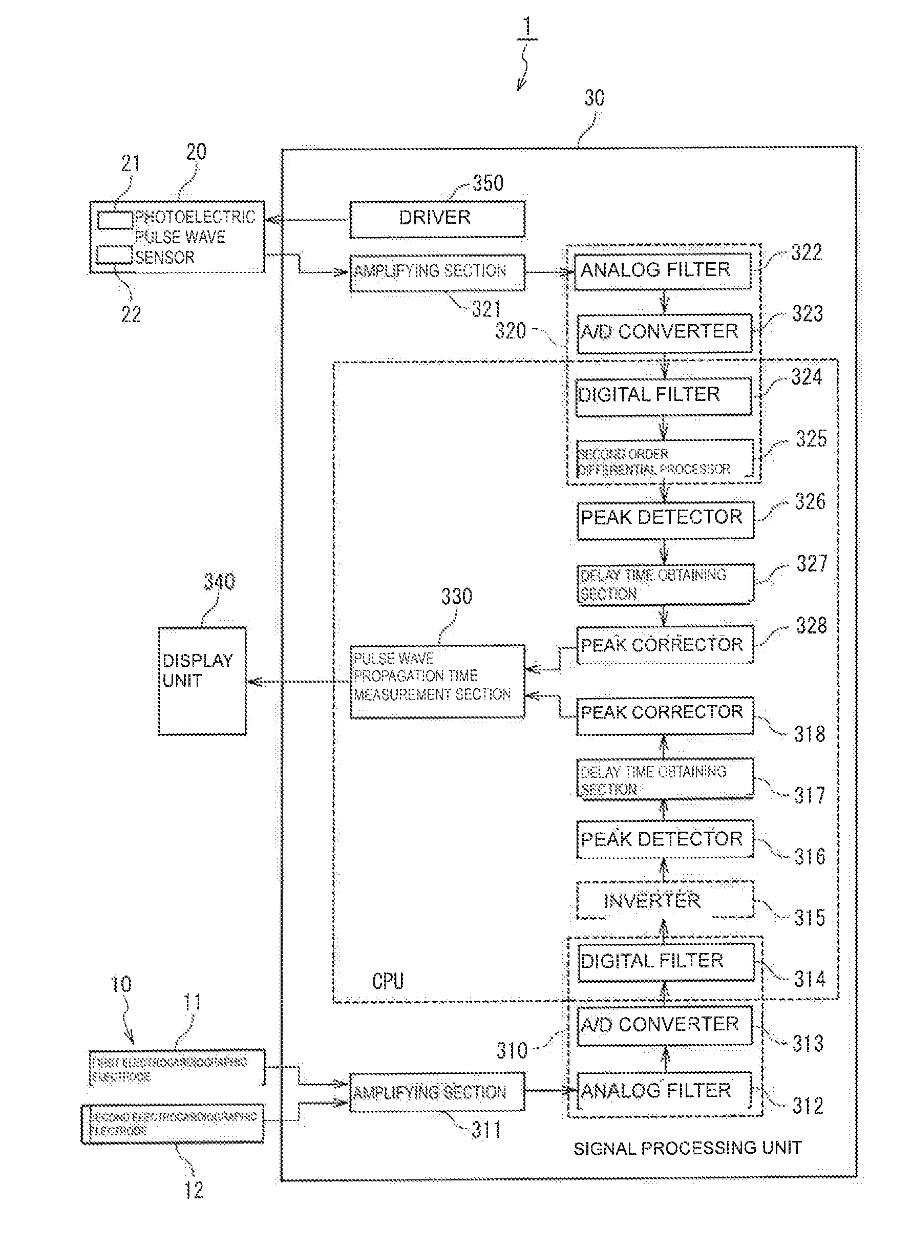
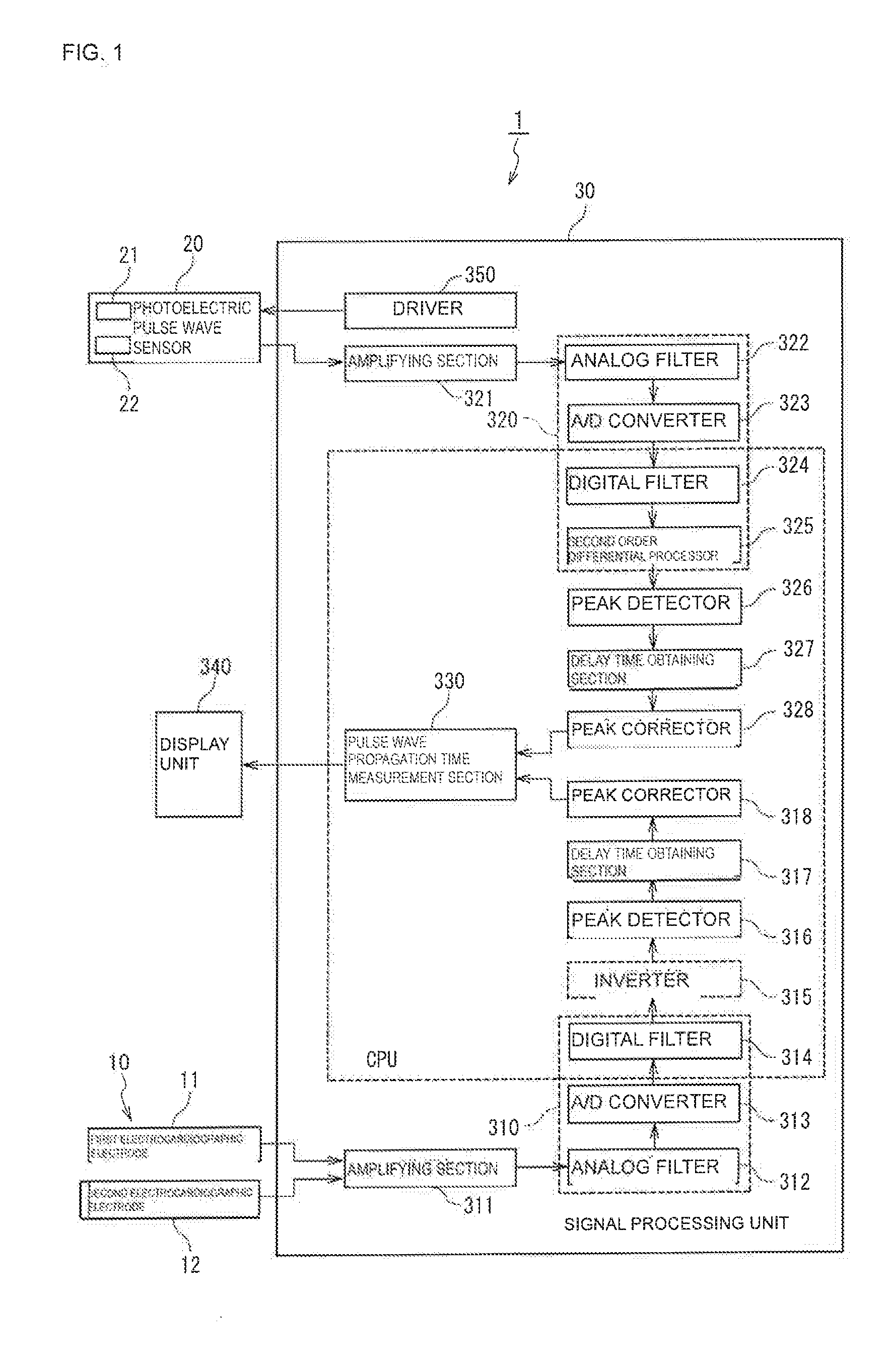
[0033]First, a configuration of a pulse wave propagation time measurement device 1 will be described with reference to FIG. 1. FIG. 1 is a block diagram illustrating the configuration of the pulse wave propagation time measurement device 1.

[0034]The pulse wave propagation time measurement device 1 detects an electrocardiographic signal and a photoelectric pulse wave signal, and measures a pulse wave propagation time from a time difference between an R-wave peak of the detected electrocardiographic signal (electrocardiographic wave) and a peak (rising point) of the detected photoelectric pulse wave signal (pulse wave) (see FIGS. 4 and 5). Accordingly, the pulse wave propagation time measurement device 1 includes an electrocardiographi...


PUM


Abstract

A pulse wave propagation time measurement device including a first signal processor section that filters an electrocardiographic signal detected by an electrocardiographic sensor, a second signal processor section that filters a photoelectric pulse wave signal detected by a photoelectric pulse wave sensor, peak detectors respectively that detect peaks of the electrocardiographic signal and the photoelectric pulse wave signal, delay time obtaining sections respectively that obtain a delay time of the electrocardiographic signal and of the photoelectric pulse wave signal, peak correctors respectively that correct the peaks of the electrocardiographic signal and the photoelectric pulse wave signal based on the delay time of the electrocardiographic signal and the photoelectric pulse wave signal, and a pulse wave propagation time measurement section that obtains a pulse wave propagation time from a time difference between the corrected peaks of the electrocardiographic signal and the photoelectric pulse wave signal.

Description

CROSS-REFERENCE TO RELATED APPLICATIONS[0001]The present application is a continuation of PCT / JP2014 / 051464 filed Jan. 24, 2014, which claims priority to Japanese Patent Application No. 2013-035546, filed Feb. 26, 2013, the entire contents of each of which are incorporated herein by reference.FIELD OF THE INVENTION[0002]The present invention relates to pulse wave propagation time measurement devices configured to measure pulse wave propagation times.BACKGROUND OF THE INVENTION[0003]In recent years, people have been paying more attention to maintenance and improvement of their health than before. People want to readily obtain information such as blood pressure, an electrocardiogram, a heart rate, and so on for health management. As such, Patent Document 1 discloses a portable blood pressure measuring device that measures an electrocardiographic wave and a plethysmogram to obtain a plethysmogram propagation time (pulse wave propagation time), and calculates a maximal blood pressure an...

Claims


Application Information

Patent Timeline
Patent Type & Authority Applications(United States)
IPC IPC(8): A61B5/021A61B5/0456A61B5/0452A61B5/0245A61B5/352
CPCA61B5/02125A61B5/0245A61B5/0456A61B5/0452A61B5/02416A61B5/7289A61B5/352A61B5/349
Inventor SHIMUTA, TORUHAYASHI, TAKANORI
Owner MURATA MFG CO LTD
Why Eureka
Try Eureka