Vehicle body structure

a technology for vehicles and body parts, applied in the direction of roofs, bumpers, pedestrian/occupant safety arrangements, etc., can solve the problem that the thickness of the side member needs to be increased

Active Publication Date: 2015-12-24
TOYOTA JIDOSHA KK
View PDF3 Cites 5 Cited by
  • Summary
  • Abstract
  • Description
  • Claims
  • Application Information

AI Technical Summary

Benefits of technology

[0007]The present invention thereby provides a vehicle body structure capable of reducing concentration of load at a side member when the load is input along the vehicle front-rear direction.
[0009]In the above aspect, the vehicle front-rear direction outside end portion of the upper member has a different position in the vehicle up-down direction from the position in the vehicle up-down direction of the vehicle front-rear direction outside end portion of the side member, and the vehicle front-rear direction outside end portion of the upper member and the vehicle front-rear direction outside end portion of the side member are coupled together by the coupling member. The vehicle front-rear direction inside end portion of the crash box is joined to the coupling member. Thus, when load is input to the vehicle along the vehicle front-rear direction by, for example, a frontal collision or a rear face collision, load that is not fully absorbed by the crash box is transmitted not only to the side member but also transmitted to the upper member through the coupling member. Concentration of load at the side member is accordingly reduced.
[0011]In the above configuration, the center line passing through the centroid of the bumper reinforcement, joined to the vehicle front-rear direction outside end portion of the crash box, and the center line passing through the centroid of the crash box are at the same position in the vehicle up-down direction. Thus, load input to the bumper reinforcement along the vehicle front-rear direction by, for example, a frontal collision or a rear face collision is efficiently transmitted to the coupling member through the crash box.
[0013]In the above configuration, the bumper reinforcement is joined to the vehicle front-rear direction outside end portion of the crash box, and the vehicle front-rear direction inside end portion of the crash box is joined to the coupling member further to the vehicle lower side than the vehicle up-down direction center portion of the coupling member. Thus, pedestrian protection performance, in which the legs of a pedestrian are protected in the event of a frontal collision or a rear face collision of the vehicle with the pedestrian, is improved.
[0017]In the above configuration, the fastening point of the vehicle front-rear direction inside end portion of the crash box, which extends toward the side member, to the coupling member is provided at the same position in the vehicle up-down direction as the center line passing through the centroid of the side member. Thus, load input through the crash box to the coupling member along the vehicle front-rear direction by, for example, a frontal collision or a rear face collision is efficiently transmitted to the side member.

Problems solved by technology

However, in such a configuration, collision load that is not fully absorbed by the crash box in the event of a frontal collision of the vehicle is transmitted unmodified to the front side member, such that the front side member needs to have increased plate thickness, to be reinforced by reinforcement, or the like.

Method used


Image

  • Vehicle body structure
  • Vehicle body structure
  • Vehicle body structure

Examples


Embodiment Construction

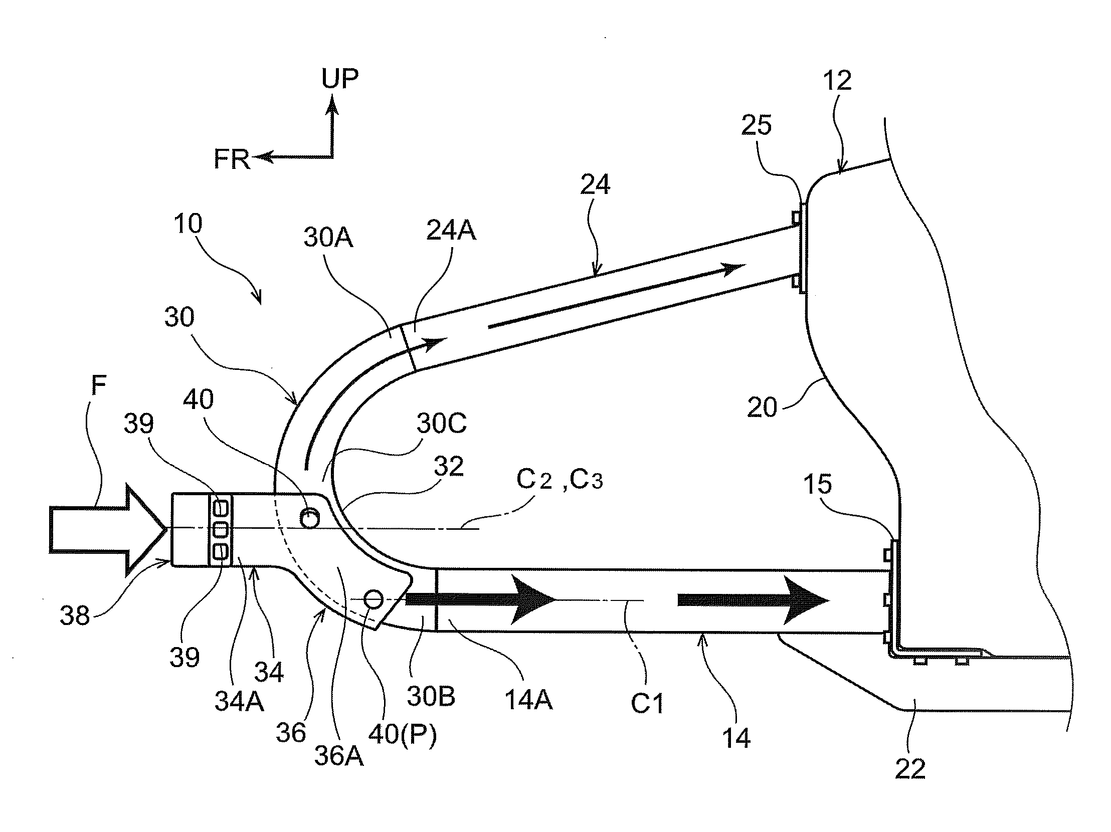
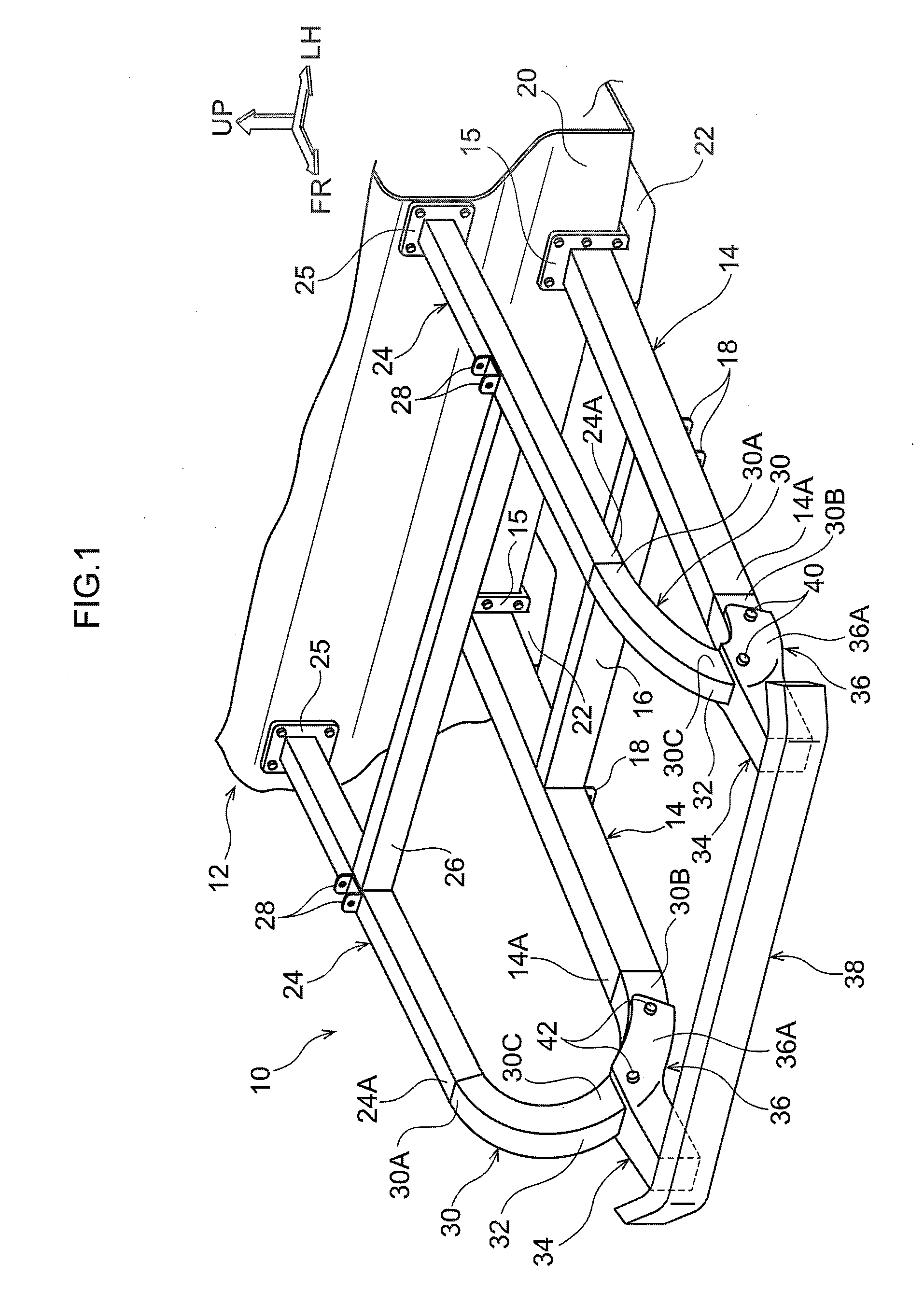
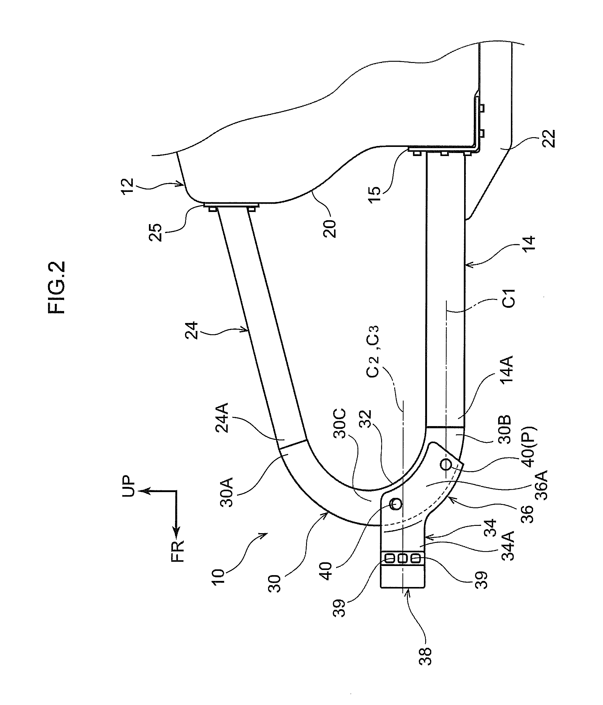
[0023]Detailed explanation follows regarding an exemplary embodiment, based on the drawings. Note that for ease of explanation, in each of the drawings the arrow UP indicates the vehicle upper direction, the arrow FR indicates the vehicle front direction, and the arrow LH indicates the vehicle left direction. Moreover, in the following explanation, unless specified otherwise, reference to the front-rear, up-down, and left-right directions indicate front-rear in the vehicle front-rear direction, up-down in the vehicle up-down direction, and left-right in the vehicle left-right direction (vehicle width direction). A vehicle body structure 10 according to the present exemplary embodiment may be applied to a front section side or a rear section side of a vehicle 12; however, application to the front section side of the vehicle 12 is explained herein as an example.

[0024]As illustrated in FIG. 1 to FIG. 3, a pair of left and right front side members 14 are disposed extending along the veh...


PUM


Abstract

A vehicle body structure includes: a side member that is disposed running along a vehicle front-rear direction; an upper member that, when viewed along the vehicle width direction, is disposed running along the vehicle front-rear direction at a vehicle upper side of the side member, and comprises a vehicle front-rear direction outside end portion that is positioned at a different position in a vehicle up-down direction from a position in the vehicle up-down direction of a vehicle front-rear direction outside end portion of the side member; a coupling member that couples the vehicle front-rear direction outside end portion of the upper member and the vehicle front-rear direction outside end portion of the side member; and a crash box that comprises a vehicle front-rear direction inside end portion that is joined to the coupling member.

Description

CROSS-REFERENCE TO RELATED APPLICATION[0001]This application is based on and claims priority under 35 USC 119 from Japanese Patent Application No. 2014-126258 filed on Jun. 19, 2014, the disclosures of which is incorporated by reference herein.BACKGROUND[0002]1. Technical Field[0003]The present invention relates to a vehicle body structure.[0004]2. Related Art[0005]Known vehicle body structures are provided with a crash box on an extension line toward the vehicle front side of a front side member (see, for example Japanese Patent No. 3974567).[0006]However, in such a configuration, collision load that is not fully absorbed by the crash box in the event of a frontal collision of the vehicle is transmitted unmodified to the front side member, such that the front side member needs to have increased plate thickness, to be reinforced by reinforcement, or the like. Thus there is still room for improvement in structures reducing the concentration of load at a side member.SUMMARY[0007]The p...

Claims


Application Information

Patent Timeline
Patent Type & Authority Applications(United States)
IPC IPC(8): B60R19/34B60R21/34B62D21/15
CPCB60R19/34B60R2021/343B60R21/34B62D21/152B62D25/08
Inventor KUROKAWA, HIROYUKI
Owner TOYOTA JIDOSHA KK
Why Eureka
Try Eureka