Blade wheel and method for producing a blade therefor

a technology of blades and axial fixings, applied in the field of blade wheels, to avoid the danger of blade roots damage, prevent blade roots damage, and increase the security of axial fixings

Inactive Publication Date: 2015-12-24
SIEMENS AG
View PDF7 Cites 2 Cited by
  • Summary
  • Abstract
  • Description
  • Claims
  • Application Information

AI Technical Summary

Benefits of technology

[0005]A first object of the invention is to provide a blade wheel which minimizes or even avoids the abovementioned problems. A second object of the invention is to produce a blade with the aid of such a blade wheel, in particular a replacement blade during an overhaul of a turbine.
[0011]The pressure piece transmits to its blade root the force which results from tightening the respective radial connection element for that root, and thus contributes to the secured, radially outermost position of the respective blade root. The shims also prevent damage to the blade roots, in particular to their coating. The blades are thus securely fixed both axially and radially in their slots. This means that the blades can be finished within the tolerances and deviations due to inadequate fixing no longer appear. The blade wheel according to the invention makes an exact finish possible, as the blades can no longer move within the slots.
[0012]Preferably, the first bearing plate bears entirely against the outlet-side blade root end face and / or the second bearing plate bears entirely against the inlet-side blade root end face. This increases the security of the axial fixing.
[0013]In a preferred configuration, the second bearing plate is connected to the inlet side of the disk element by releasable attachment elements, in particular screws. Preferably, the first bearing plate is connected to the outlet side of the disk element by non-releasable connection elements. The blade roots may thus be pushed into the slots only from the inlet side. This also avoids the danger of damage to the blade roots due to e.g. further screwing in of the first bearing plate.
[0017]In operation, the dimensions of both the rotor and the surrounding components change, generally as a consequence of the acceleration. For that reason, the blades to be exchanged during an overhaul must be adapted to the new changed conditions. Hitherto, this was possible only with great expenditure. The method according to the invention causes the replacement blades to be ready prior to the turbine overhaul and these ready replacements can be installed directly. This avoids an undesired extension of the overhaul and particularly of the time it requires. If the method is used in conjunction with the blade wheel according to the invention, then all of the blades can be provided with the same length, so that variation in blade length is minimized. Preferably, as an additional step, a current-design deviation, between the current blade length and the design blade length, is determined. It is thus possible to manufacture within tolerances.

Problems solved by technology

This means that the blades can be finished within the tolerances and deviations due to inadequate fixing no longer appear.

Method used


Image

  • Blade wheel and method for producing a blade therefor
  • Blade wheel and method for producing a blade therefor
  • Blade wheel and method for producing a blade therefor

Examples


Embodiment Construction

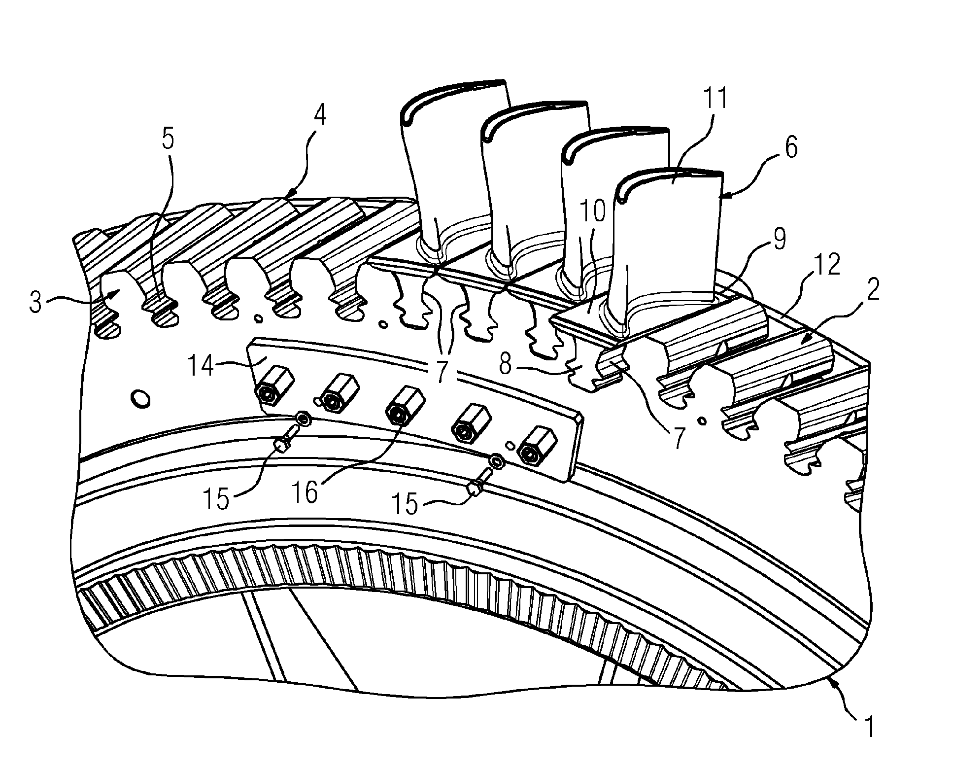
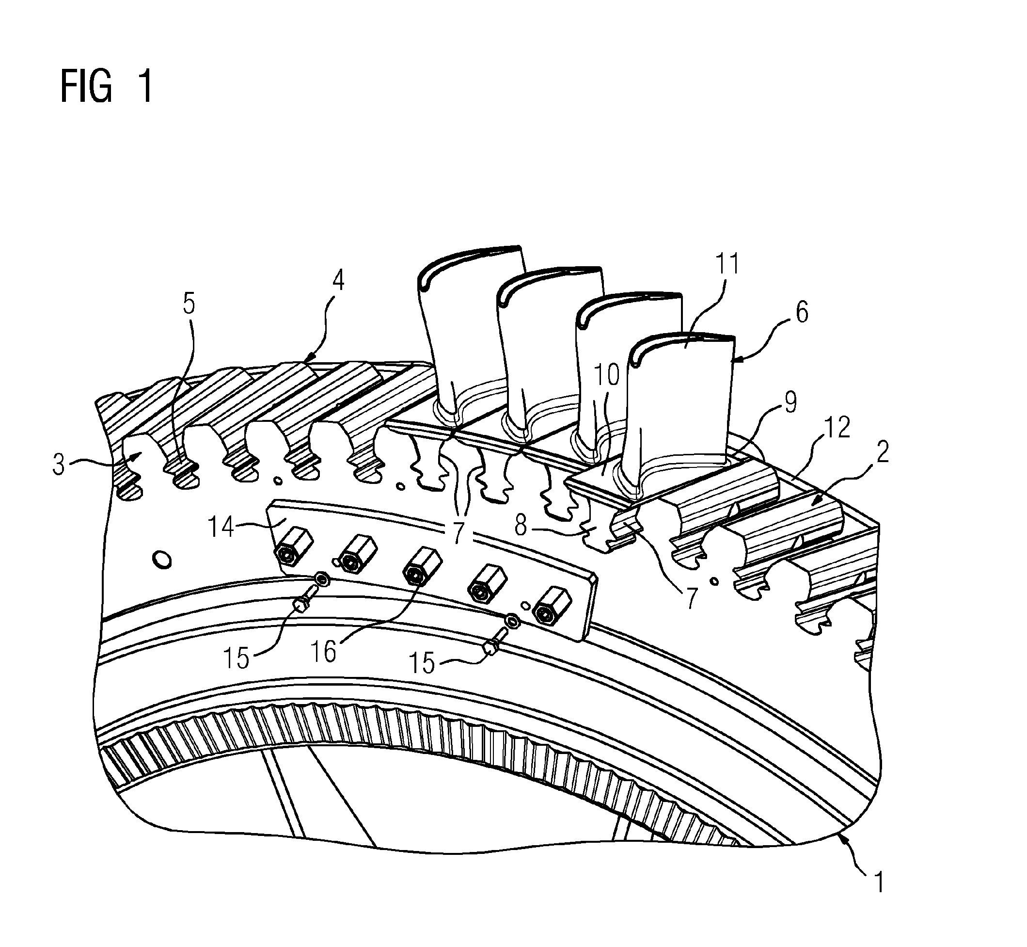
[0023]Referring to FIG. 1, a blade wheel according to the invention has a rotor disk 1 with a disk element 2, which comprises an inlet side 3 and an opposite outlet side 4 and essentially axial direction slots 5 distributed around the circumference of the disk element. Furthermore, the blade wheel comprises multiple blades 6, each having a blade root 7, an outlet-side blade root end face 9 and an inlet-side blade root end face 8, a blade root upper surface or platform 10 and a blade upper 11. The blade root 7 is configured to be inserted into the respective slot starting from the inlet side 3 of the disk element 2 and then is secured in the slot 5.

[0024]There is a first bearing plate 12 on the outlet side which is shaped as an annulus and is positioned such that the outlet-side blade root end face 9 entirely bears against the first bearing plate 12. However, the outlet-side blade root end face 9 may partially bear against the first bearing plate 12. The first bearing plate 12 is con...


PUM

PropertyMeasurementUnit
circumferenceaaaaaaaaaa
pressureaaaaaaaaaa
forceaaaaaaaaaa

Abstract

A turbine blade wheel includes a wheel disk with a disk element (2) including an inlet side (3), an opposite outlet-side (4), substantially axial slots (5) distributed over the disk circumference, and vanes (6) in the slots. Each vane includes a vane root (7), an outlet-side vane root end surface (9) and an inlet-side vane root end surface (8). The vane root (7) is at the inlet side (3) of the disk element (2) for mounting in its respective slot (5). A first bearing plate (12) is provided on the outlet side (4) of the disk element. At least one pressure piece shim (13) is provided in the slot (5). A second bearing plate (14) is provided on the inlet side (3). The disk element (2) is connected to the second bearing plate (14) by a radial connecting element (16) that is pressed to act on the shim in the slot to urge the root of the vane base (7) in the slot (5) to an outermost radial position. Further a method for producing a vane using such a blade wheel is disclosed.

Description

CROSS-REFERENCE TO RELATED APPLICATIONS[0001]The present application is a 35 U.S.C. §§371 national phase conversion of PCT / EP2013 / 072125, filed Oct. 23, 2013, which claims priority of European Patent Application No. 13155707.6, filed Feb. 19, 2013, the contents of which are incorporated by reference herein. The PCT International Application was published in the German language.TECHNICAL BACKGROUND[0002]The invention relates to a blade wheel particularly for a turbine, the blade wheel, comprising a rotor disk having a disk element. The disk element comprises an inlet side and, opposite the inlet side, an outlet side and a periphery having essentially axial slots distributed over its circumference. Multiple turbine blades are distributed with one in each slot. Each turbine blade is comprised of a blade root, an outlet-side blade root end face and an inlet-side blade root end face. The blade root is to be installed in the respective slot from the inlet side of the disk element. The inv...

Claims


Application Information

Patent Timeline
Patent Type & Authority Applications(United States)
IPC IPC(8): F01D5/30F01D5/12F01D5/32F01D5/02
CPCF01D5/3015F01D5/02F01D5/12Y10T29/49337F05D2220/30F05D2230/50F01D5/326F05D2260/821F01D25/285F05D2230/80F05D2230/10
Inventor FOHRIGEN, ANDREASJUNG, ENNOKOCH, CHRISTIAN ALBRECHTWEBER, UDO
Owner SIEMENS AG
Why Eureka
Try Eureka