

Temperature control
a temperature control and temperature technology, applied in the field of tanks, can solve the problems of brittle fracture of conventional shipbuilding and structural materials, insufficient pressure to be maintained in the tank, and brittle fracture, so as to reduce the effect of liquefied gas in the pressure vessel, minimize or alleviate the effect of brittle fractur
Inactive Publication Date: 2013-12-12
AKER ENG & TECH
View PDF10 Cites 0 Cited by
- Summary
- Abstract
- Description
- Claims
- Application Information
AI Technical Summary
Benefits of technology
The current invention is a new way to increase the pressure in a container containing liquefied gas. This method helps to reduce the risk of accidental leakage of cryogenic liquid, which is a big improvement over previous methods.
Problems solved by technology
Leakage of liquid with low temperature will due to its large heat capacity almost immediately cause brittle fracture of conventional shipbuilding and structural materials.
The limitation of this technique is that sufficient pressure needs to be maintained in the tank to overcome the hydrostatic head at the top of the tank.
This is done at the expense of the accidental occurrence that cryogenic liquid may leak and cause brittle fracture.
Method used
View moreImage
Smart ImageViewing Examples

Examples
Embodiment Construction
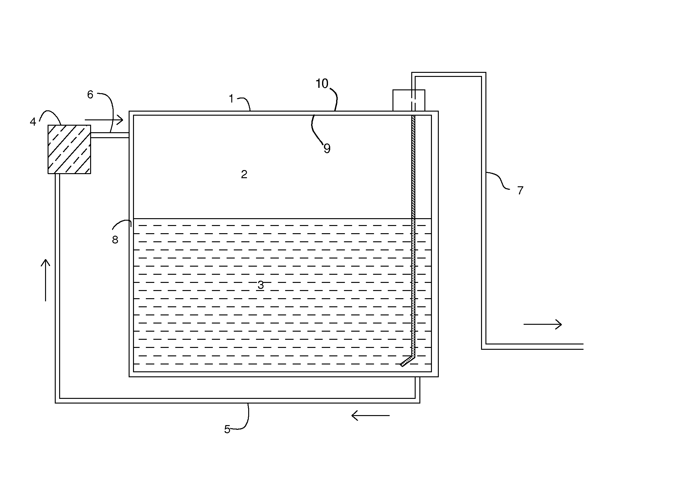
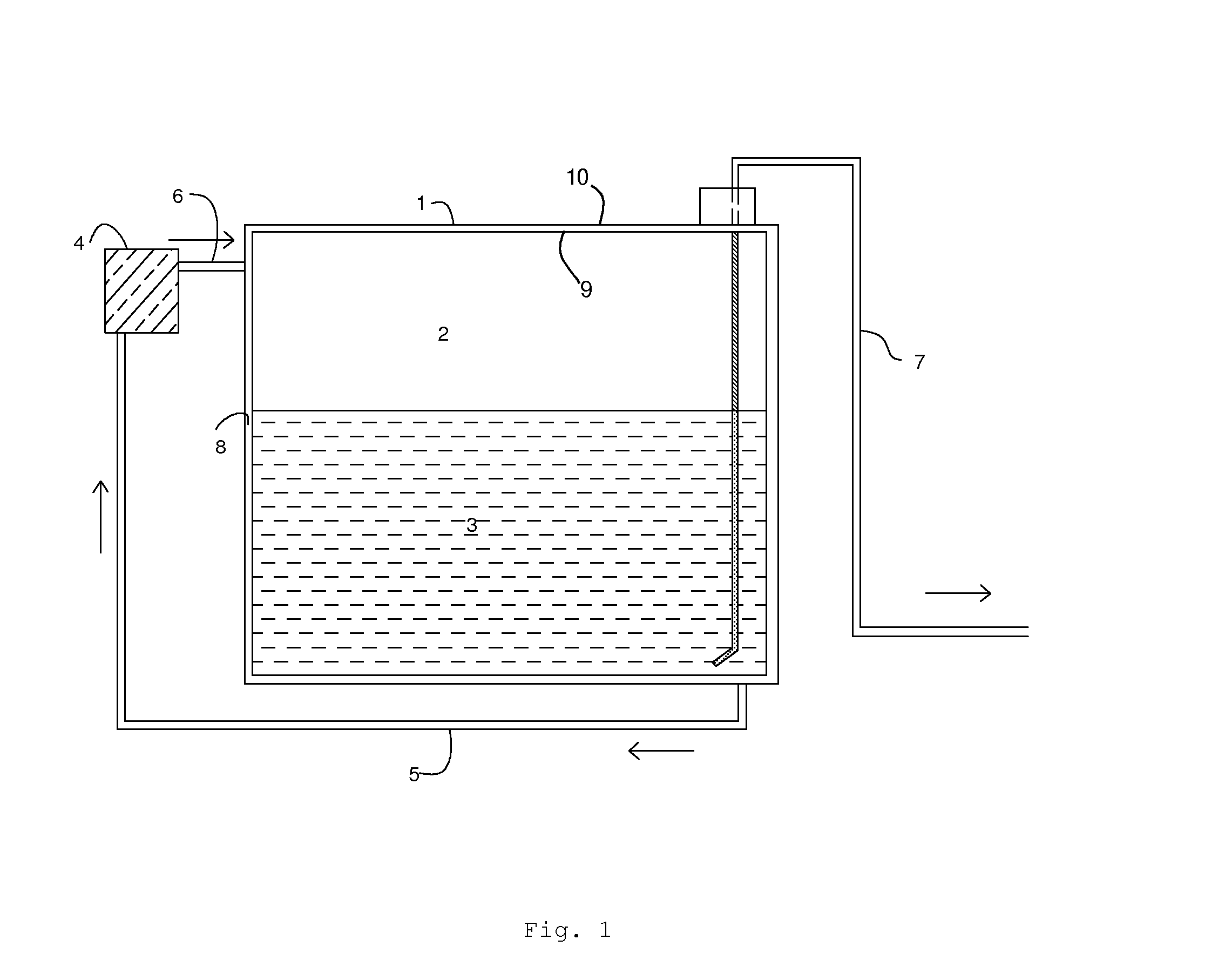
[0020]FIG. 1 shows a double barrier (inner 9 and outer 10 barrier walls) pressure vessel 1 containing the gas phase of the stored medium 2 and the liquid phase 3. The external heating unit 4 (in this case intended to be a heat exchanger) heats a fluid which circulates through a pipe 6 into the inter-barrier space 8 through a return pipe 5 and back into the heat exchanger 4. The increased evaporation from the liquid 3, due to the heat provided by the circulating fluid, causes increased pressure in the gas phase 2. This in turn provides sufficient pressure to overcome the hydrostatic head required to expel the stored liquid 3 through the pipe 7.
Login to View More PUM
 Abstract
The present invention provides a method for increasing the internal pressure of a pressure vessel (1) containing a medium being present in both a liquid (3) and gaseous (2) phase, the vessel comprising one inner (9)and one outer (10) fluid tight barrier, said barriers being separated by an inter-barrier space (8), comprising the steps of: —circulating a suitable fluid through both the inter-barrier space and a heating unit; and —heating the fluid by the heating unit.
Description
TECHNICAL FIELD[0001]The present invention relates to tanks for storage and transportation of fluids such as hydrocarbons, including low temperature liquefied natural gas. This includes tanks for storage and transportation including mobile and fixed fuel tanks for marine and onshore applications.BACKGROUND OF THE INVENTION[0002]For a number of applications liquefied gas may be conveniently stored in pressure vessels. One advantage is that in such tanks the evaporating liquid may be retained until a convenient time when the gas phase is required for consumption. For use in combustion engines it is in particular required that hydrocarbon gas needs to be delivered at controlled pressure. Another aspect is that from a tank under sufficient pressure liquid can be drained above the level of the stored liquefied gas without the use of a pump. This allows the liquid to be drained from the tank without allowing apertures below the liquid surface from which the liquid may be drained by gravit...
Claims
Login to View More Application Information
Patent Timeline
 IPC IPC(8): F17C9/02
CPCF17C9/02F17C2201/052F17C2201/054F17C2203/03F17C2203/0629F17C2203/0682F17C2221/033F17C2221/035F17C2223/0153F17C2223/0161F17C2223/033F17C2227/0313F17C2227/0316F17C2227/0323F17C2227/0381F17C2260/036F17C2270/0105F17C2270/0134
InventorSELE, ARNE BARRETTLUND, TRYGVE JOHANNES
OwnerAKER ENG & TECH