Actuator unit

a technology of actuator unit and actuator body, which is applied in the direction of shock absorber, fluid coupling, servomotor, etc., can solve the problems of difficult to converge the thrust output of the actuator unit may become extremely large, etc., to suppress the lateral direction the effect of reducing the vibration of the vehicle body

Inactive Publication Date: 2015-12-24
KYB CORP
View PDF11 Cites 2 Cited by
  • Summary
  • Abstract
  • Description
  • Claims
  • Application Information

AI Technical Summary

Benefits of technology

[0005]To suppress lateral direction vibration of a vehicle body of a railway vehicle using the actuator unit disclosed in JP2010-65797A, lateral direction acceleration of the vehicle body is detected using an acceleration sensor, and the actuator unit is caused to output thrust that counterbalances the detected acceleration. In so doing, the vibration of the vehicle body can be suppressed. In this case, when the railway vehicle travels in a curved section, for example, steady acceleration acts on the vehicle body, and as a result, the thrust output by the actuator unit may become extremely large due to effects from noise and drift input into the acceleration sensor.

Problems solved by technology

In this case, when the railway vehicle travels in a curved section, for example, steady acceleration acts on the vehicle body, and as a result, the thrust output by the actuator unit may become extremely large due to effects from noise and drift input into the acceleration sensor.
Hence, the force for returning the vehicle body to the neutral position becomes excessive such that the vehicle body passes the neutral position and displaces to an opposite side, and as a result, it may be difficult to converge the vibration of the vehicle body.

Method used


Image

  • Actuator unit
  • Actuator unit
  • Actuator unit

Examples


Embodiment Construction

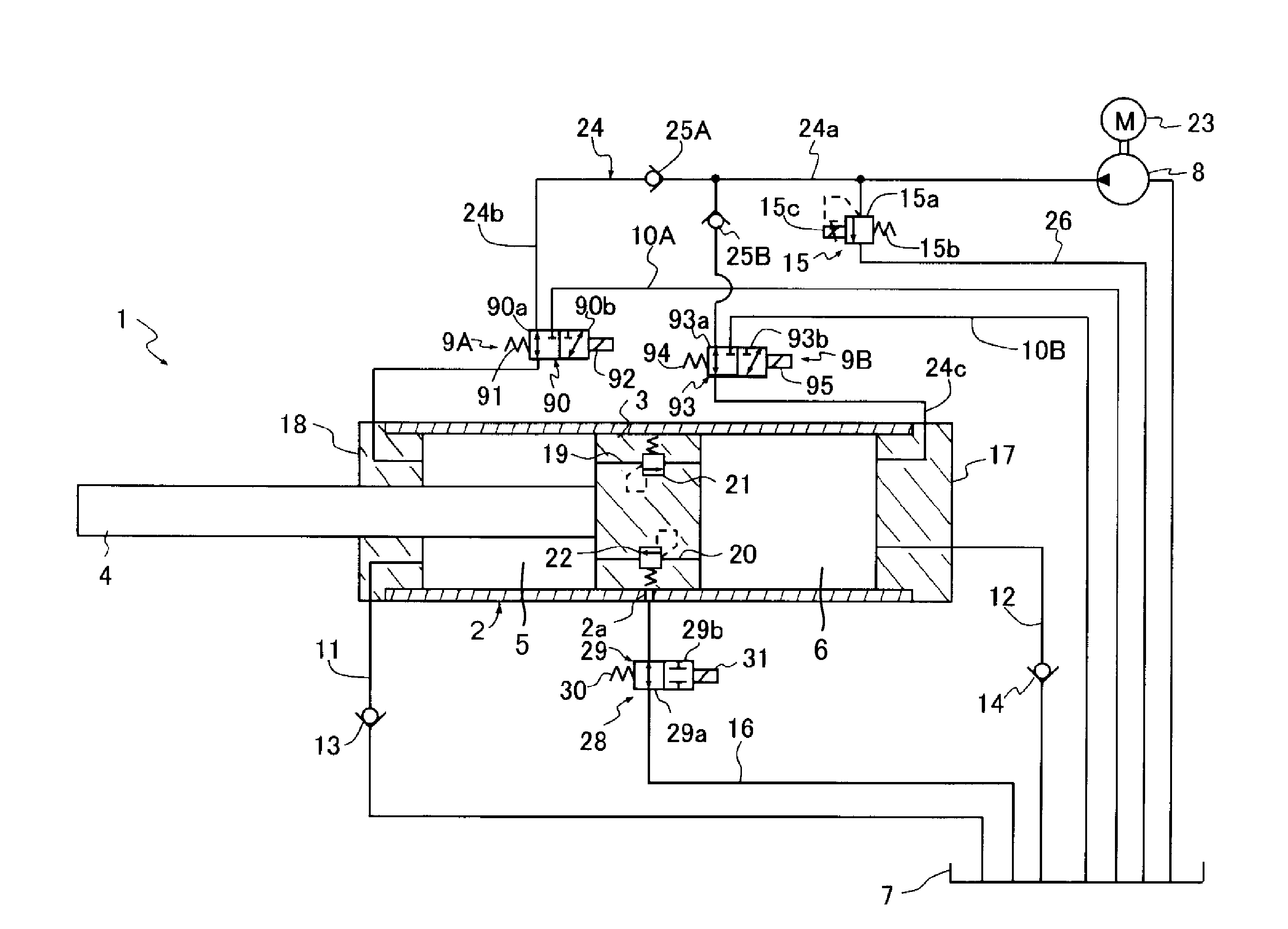
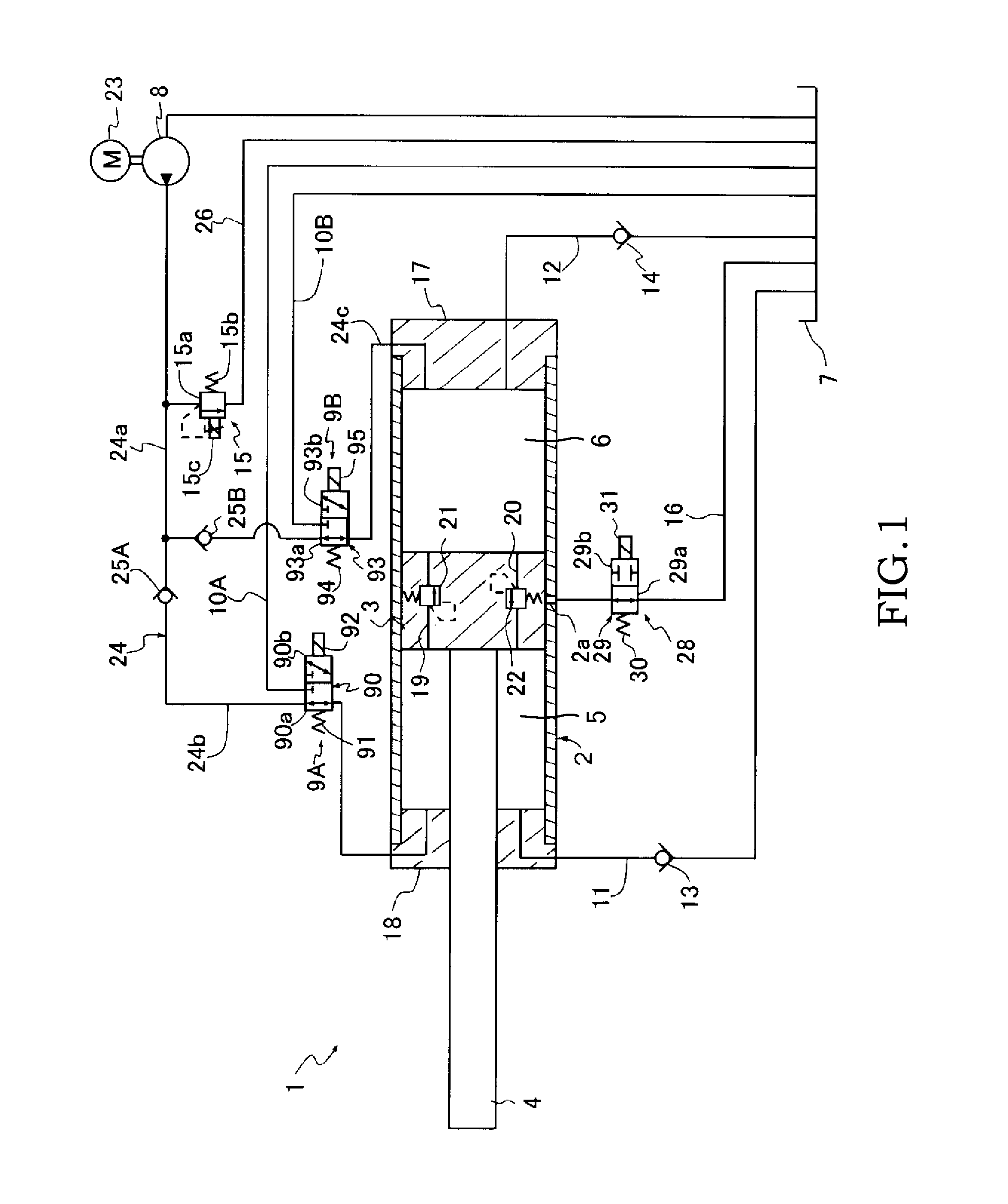
[0015]An embodiment of the present invention will be described below with reference to the attached figures. As shown in FIG. 1, an actuator unit 1 according to this embodiment of the present invention includes a cylinder 2; a piston 3 slidably inserted into the cylinder 2, the piston 3 defining two chambers (a rod side chamber 5 and a piston side chamber 6) in the cylinder 2; a rod 4 inserted into the cylinder 2 and coupled to the piston 3; a tank 7; a pump 8; a supply passage 24 provided between the pump 8 and the two chambers (the rod side chamber 5 and the piston side chamber 6) so as to allow a working fluid discharged from the pump 8 to be supplied to the two chambers (the rod side chamber 5 and the piston side chamber 6); discharge passages 10A, 10B provided between each of the two chambers (the rod side chamber 5 and the piston side chamber 6) and the tank 7 so as to allow the two chambers (the rod side chamber 5 and the piston side chamber 6) to communicate with the tank 7;...


PUM


Abstract

An actuator unit includes two chambers defined in the cylinder; a supply passage allowing a working fluid discharged from the pump to be supplied to the two chambers; a discharge passage allowing the two chambers to communicate with the tank; a direction control valve configured to selectively communicate each of the two chambers with one of the pump and the tank; a control passage that branches from the supply passage on a side of the pump rather than the direction control valve so as to communicate the pump with the tank; a variable relief valve provided on the control passage, the variable relief valve opening so as to allow the working fluid to flow from the supply passage toward the tank when a pressure in the supply passage reaches the valve opening pressure; and a center passage that communicates the tank with an interior of the cylinder.

Description

TECHNICAL FIELD[0001]The present invention relates to an actuator unit.BACKGROUND ART[0002]An actuator unit is used in a railway vehicle, for example, by being interposed between a vehicle body and a truck in order to suppress left-right direction vibration relative to an advancing direction of the vehicle body.[0003]JP2010-65797A discloses an actuator unit including: a cylinder; a piston slidably inserted into the cylinder; a rod inserted into the cylinder and coupled to the piston; a rod side chamber and a piston side chamber defined within the cylinder by the piston; a tank; a first opening / closing valve provided on midway of a first passage that communicates the rod side chamber with the piston side chamber; a second opening / closing valve provided on midway of a second passage that communicates the piston side chamber with the tank; a pump that is configured to supply a working fluid to the rod side chamber; a motor that is configured to drive the pump; an exhaust passage that c...

Claims


Application Information

Patent Timeline
Patent Type & Authority Applications(United States)
IPC IPC(8): F15B11/10
CPCF15B2211/30505F15B11/10B61F5/24F15B2211/30565F15B2211/8613F16F9/00B61F5/245F15B2211/40F15B2211/50518F15B2211/5157F15B2211/526F16F9/19F15B11/121
Inventor OGAWA, TAKAYUKI
Owner KYB CORP
Why Eureka
Try Eureka