Simple stereoscope for allowing side-by-side image to be seen as three-dimensional image

a stereoscope and side-by-side technology, applied in the field of stereoscopes, can solve the problems of increasingly produced and consumed three-dimensional images, and achieve the effects of reducing manufacturing costs, less tired, and high quality

Inactive Publication Date: 2015-12-24
GO4D TECH
View PDF0 Cites 7 Cited by
  • Summary
  • Abstract
  • Description
  • Claims
  • Application Information

AI Technical Summary

Benefits of technology

[0020]Thanks to a structure that can vary the vertical separation distance of two lenses with respect to an object to be viewed in 3D, users can adjust the vertical separation distance according to the focal lengths of their eyes. When the two lenses are separated at an optimal separation distance from the object to be viewed, the object can be most clearly shown. Accordingly, even if any user uses the stereoscope of the present invention, the stereoscope can enable the user to optimally adjust a customized focal length suitable for his/her eye characteristic, so that the user can view a clear three-dimensional image.
[0021]As mentioned above, intervals between people's eyes are different from each other. However, the stereoscope proposed by the present invention has a structure in which the horizontal separation distance between two lenses can be varied, so that e

Problems solved by technology

Recently, three-dimensional images have been increasingly produced and consumed due to the attraction thereof.
Furthermore, since a user usually does not know the interval bet

Method used


Image

  • Simple stereoscope for allowing side-by-side image to be seen as three-dimensional image
  • Simple stereoscope for allowing side-by-side image to be seen as three-dimensional image
  • Simple stereoscope for allowing side-by-side image to be seen as three-dimensional image

Examples


first embodiment

(1) First Embodiment

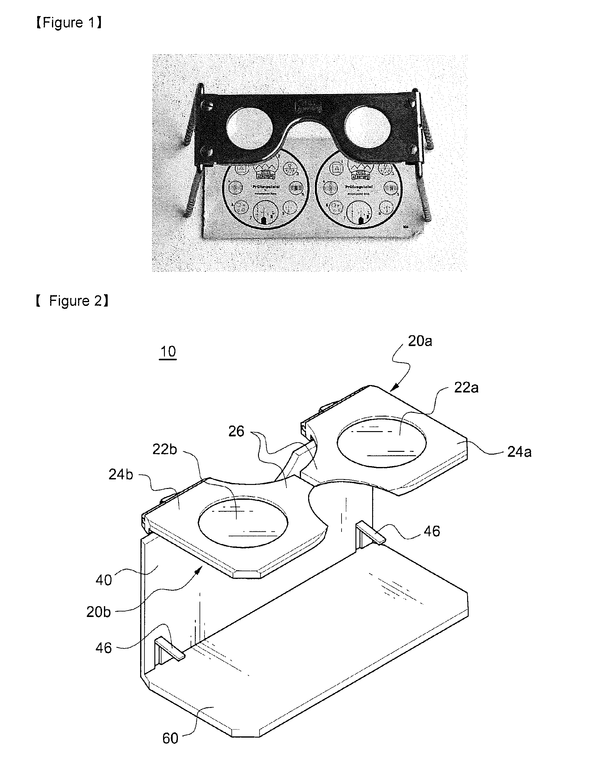
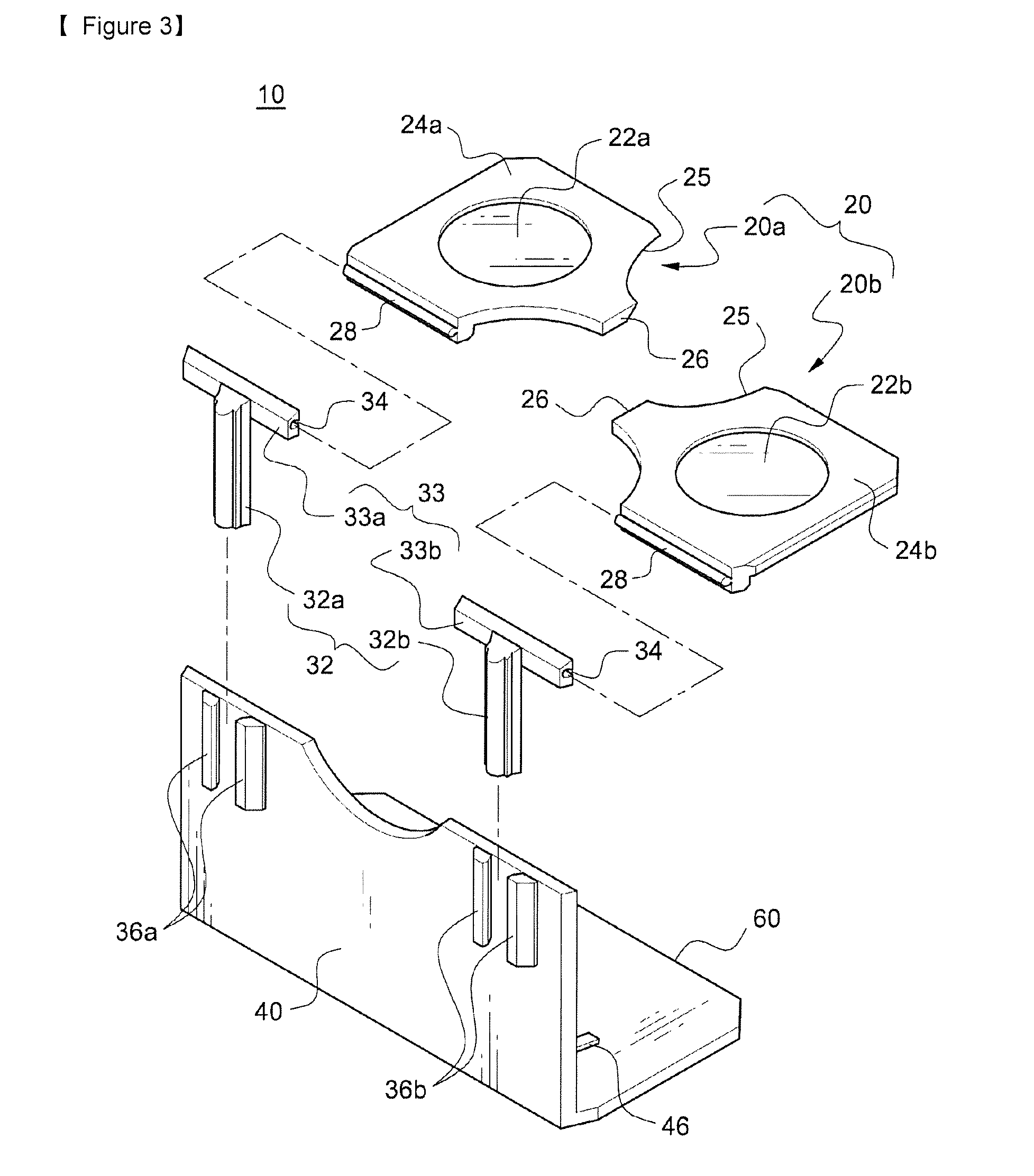
[0028]FIGS. 2 to 4 illustrate a stereoscope 10 according to a first embodiment of the present invention. The stereoscope 10 has a lens height adjusting part 30. The lens height adjusting part 30 includes two guide parts 36a and 36b that have the same structure and are mounted on the left and right sides of the rear surface of a vertical support member 40 in the shape of a plate. Each guide part 36a or 36b has a structure in which two guide bars vertically extending to be parallel to each other are spaced a predetermined distance apart from each other in the horizontal direction and secured to the rear surface of the vertical support member 40. Each guide part 36a or 36b provides a liner guide groove in the vertical direction.

[0029]First and second height adjusting bars 32a and 32b are inserted into the guide grooves of the two guide parts 36a and 36b, respectively, so as to slide in the vertical direction. The height adjusting bars 32a and 32b are used to adjust ...

second embodiment

(2) Second Embodiment

[0037]FIGS. 5 to 7 illustrate a stereoscope 100 according to a second embodiment of the present invention. The stereoscope 100 is the same as the stereoscope 10 of the first embodiment except elements constituting a lens interval adjusting part and a structure for holding a smart phone 70.

[0038]The structure of the lens interval adjusting part 150 of the stereoscope 100 is as follows. Openings 152a and 152b that have a predetermined width are vertically formed through rear edge portions 153a and 153b of first and second lens frames 124a and 124b along the rear edges, respectively. U-shaped suspenders 154a and 154b are provided on the upper ends of first and second height adjusting bars 132a and 132b, respectively, to correspond to the openings 152a and 152b. When each one of vertical parts of the U-shaped suspenders 154a and 154b is inserted into the openings 152a and 152b, the rear edge portions 153a and 153b which define the openings 152a and 152b are inserted...

third embodiment

(3) Third Embodiment

[0041]FIGS. 8 to 12 are: an assembled perspective view illustrating the structure of a stereoscope 200 according to a third embodiment of the present invention; a view illustrating a state in which eyeglass temples 230a and 230b are folded; a view illustrating a state in which the stereoscope is mounted on an image reproduction device 70 such as a smart phone; a perspective view illustrating a state in which two lenses 22a and 22b are disassembled; and a view illustrating states in which the interval between the two lenses 22a and 22b is adjusted to the maximum distance and the minimum distance, respectively.

[0042]The stereoscope 200, according to the third embodiment, differs from those according to the two aforementioned embodiments in that the overall shape of the stereoscope 200 is designed as an eyeglass shape, the left and right eyeglass temples 230a and 230b are foldable, the interval between the two lenses 22a and 22b can be adjusted, but the heights of t...


PUM


Abstract

A simple stereoscope for viewing a side-by-side image is disclosed. The stereoscope (10, 100) comprises lens height-adjusting parts (30) for holding a first lens part and a second lens part such that the vertical heights of a first lens and a second lens can be adjusted within the range from a first height to a second height while the first lens and the second lens are placed side to side so as to be parallel with a horizontal direction. Furthermore, the stereoscope can further comprise lens interval-adjusting parts (50, 150) capable of adjusting horizontal intervals between the center of the first lens and the center of the second lens within a predetermined range. The stereoscope can also be formed by comprising an eyeglass frame and eyeglass temples and allowing a horizontal diameter of a lens mounting part of the eyeglass frame to be larger than that of the lenses so as to adjust the horizontal intervals of the two lenses.

Description

TECHNICAL FIELD[0001]The present invention relates to a stereoscope used as a tool for viewing a three-dimensional image and, more specifically, to a simple stereoscope for allowing side-by-side stereo images to be shown as a three-dimensional image.BACKGROUND ART[0002]When a person observes an object with his / her eyes, images of the same object that are viewed at slightly different angles while the left and right eyes are separated from each other are focused on the retinas of both the eyeballs and then transferred to the brain. The person's brain then composites the two received images and recognizes the perspective of stereoscopic space. Recently, three-dimensional images have been increasingly produced and consumed due to the attraction thereof. One of the conventional methods for enabling a person to view a three-dimensional image is to represent the same object as two images with a slight view-angle deviation and then enable the two images to be shown to a person's two eyes, r...

Claims


Application Information

Patent Timeline
IPC IPC(8): G02B27/22
CPCG02B27/2228G02B27/027G02B27/04G02B30/37G02F1/133512G02B30/25G02B30/34
Inventor CHOI, JAE HYUK
Owner GO4D TECH
Why Eureka
Try Eureka