Heart valve repair devices for placement in ventricle and delivery systems for implanting heart valve repair devices

Active Publication Date: 2015-12-31
MITRALIX
View PDF7 Cites 81 Cited by
  • Summary
  • Abstract
  • Description
  • Claims
  • Application Information

AI Technical Summary

Benefits of technology

[0010]In some embodiments, the implantable heart valve repair device has a stabilizing section that consists only of a ventricular stabilizing section that is adapted to engage tissue only on the ventricular side of the valve. The ventricular stabilizing section may consist essentially of, or consist only of, or may be in the form of a ventricular winding having a generally spiral shape as described above for drawing chords associated with the heart valve together. The ventricular winding is adapted to engage tissue only on the ventricular side of the valve, and the ventricular winding stabilizes the device by the interaction between the ventricular winding and the chords on the ventricular side of the valve.
[0013]In some embodiments of a delivery system for implanting a heart valve repair device, the delivery system comprises an applicator tube and an internal rod within the applicator tube. The internal rod may be adapted to hold the heart valve repair device during maneuvering of the device. The delivery system is adapted to release the heart valve repair device after positioning of the heart valve repair device in the desired location. The delivery system may include a window through which all or part of the heart valve repair device may be ejected. The delivery system may also include a ramp surface for facilitating ejection of the heart valve repair device.

Problems solved by technology

The implantable heart valve repair device in these embodiments is “free of any atrial stabilizing section,” meaning that the device does not have any part that is adapted to stabilize the device by engaging tissue on the atrial side of the valve, such as the wall of the atrium or the annulus of the valve on the atrial side.

Method used


Image

  • Heart valve repair devices for placement in ventricle and delivery systems for implanting heart valve repair devices
  • Heart valve repair devices for placement in ventricle and delivery systems for implanting heart valve repair devices
  • Heart valve repair devices for placement in ventricle and delivery systems for implanting heart valve repair devices

Examples


Embodiment Construction

[0027]The Applicant's prior application US 2013 / 0006352 discloses various heart valve repair devices and methods of implanting them. The disclosure of US 2013 / 0006352 is hereby expressly incorporated herein by reference.

[0028]Certain embodiments of heart valve repair devices and methods of using them are described herein with reference to the accompanying drawings. These embodiments are only examples, as numerous variations of the invention disclosed herein are possible within the scope of the appended claims.

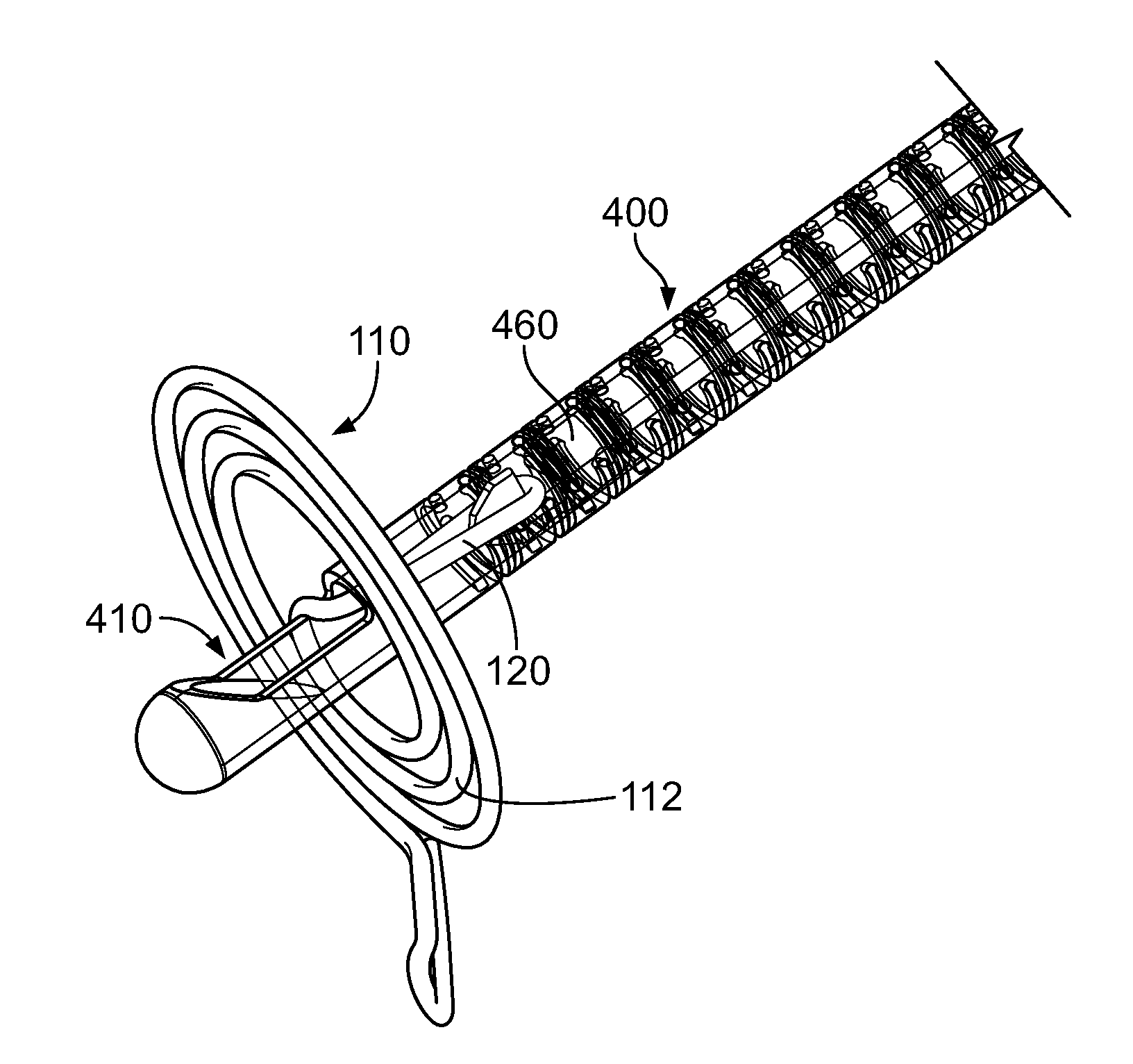
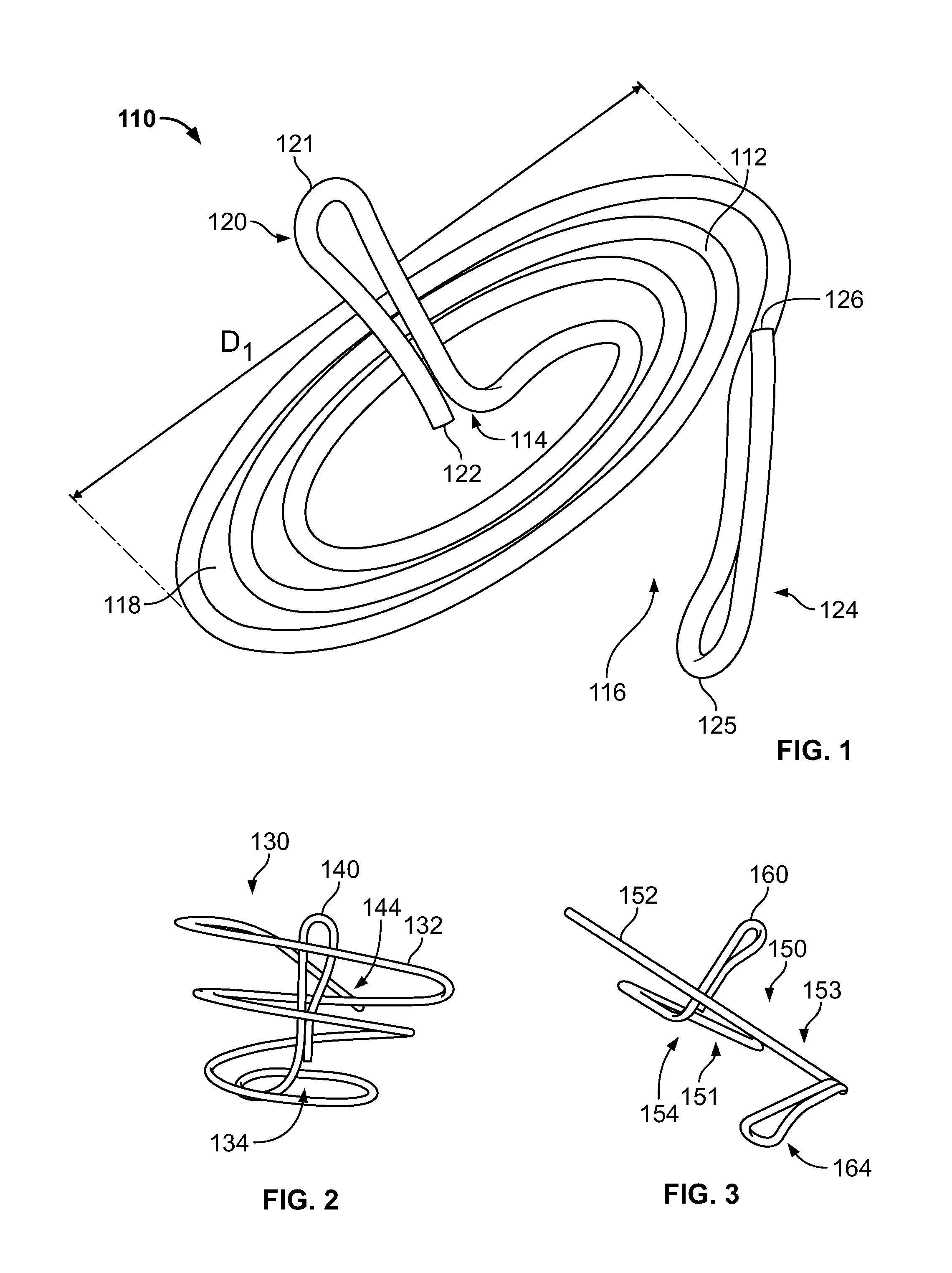
[0029]FIG. 1 shows a first embodiment of a heart valve assisting device 110. The device 110 comprises a ventricular winding 112 and a grasping element 120. As described below, the ventricular winding 112 serves the functions of both facilitating valve leaflet coaptation and stabilizing or anchoring the device with respect to the chords.

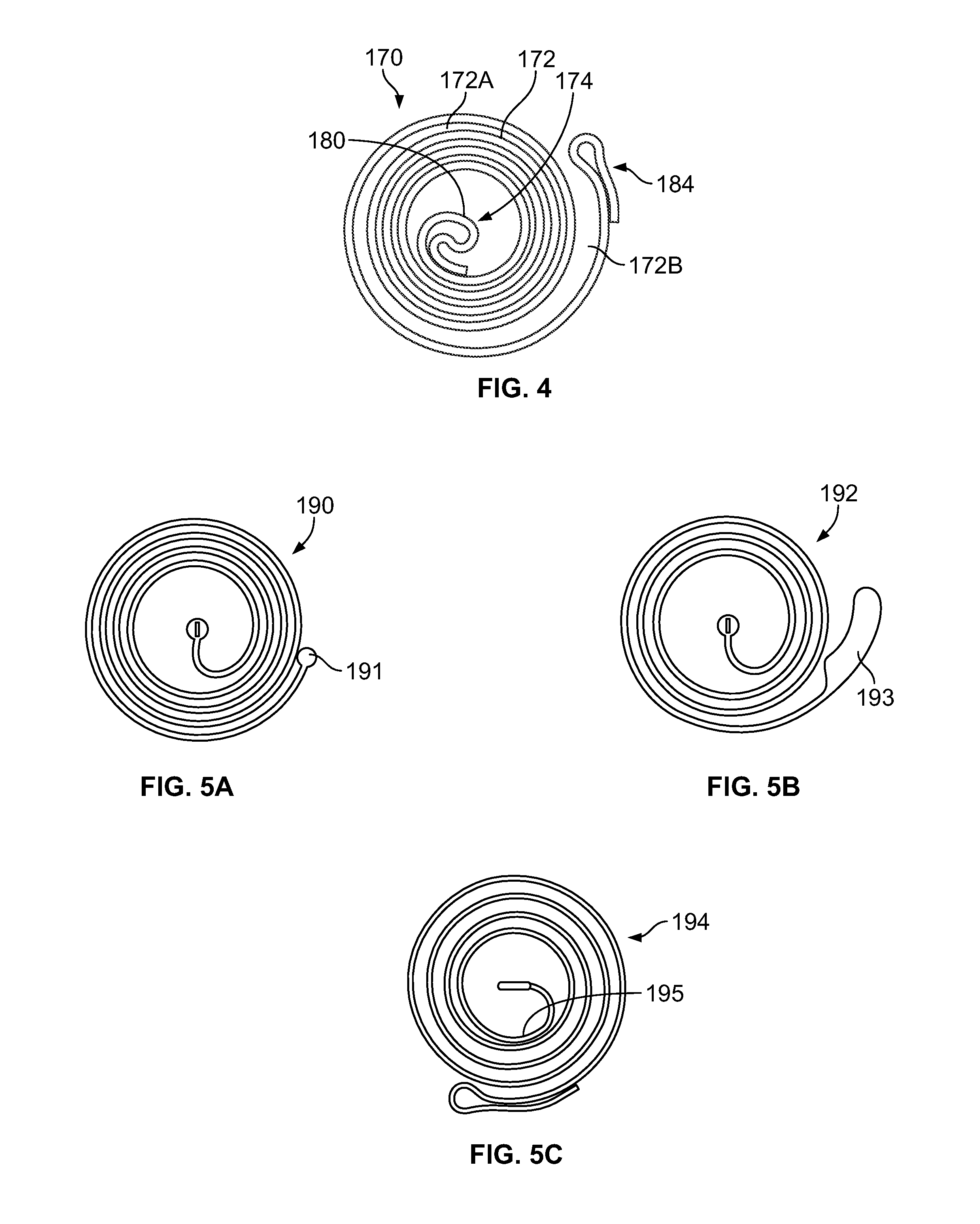
[0030]The term “spiral” is used herein to refer broadly to shapes defined by a structure forming a winding around a center wherein the winding g...


PUM


Abstract

Devices and methods for the repair of the functioning of heart valves are provided. A device may comprise a ventricular winding having a generally spiral shape, wherein the device is free of any atrial stabilizing section. A method involves positioning the device such that chords associated with the heart valve are positioned within the path of the generally spiral shape of the ventricular winding and turning the ventricular winding such that the chords move closer to the center of the ventricular winding. The ventricular winding draws the chords closer together, thereby pulling the valve leaflets closer together in order to facilitate their coaptation and proper closing. A delivery system for maneuvering and releasing a heart valve repair device comprises an applicator tube and internal rod.

Description

FIELD OF THE INVENTION[0001]The invention relates to devices and methods for the repair of the functioning of heart valves, in particular the mitral valve.BACKGROUND OF THE INVENTION[0002]Heart valves regulate the movement of blood into and out of the chambers of the heart. The mitral valve, positioned between the left atrium and the left ventricle, can be subject to a condition known as mitral regurgitation, in which the mitral valve does not close properly and some backflow of blood occurs from the left ventricle back into the left atrium. For example, a mitral valve leaflet can experience prolapse during systole, thereby inhibiting leaflet coaptation and permitting backflow of blood into the left atrium.[0003]Various procedures and devices have been proposed to address the condition of mitral regurgitation. For example, some mitral valve repair procedures involve removing a section of a valve leaflet in order to reduce its propensity for prolapse. Other procedures involve mitral ...

Claims


Application Information

Patent Timeline
Patent Type & Authority Applications(United States)
IPC IPC(8): A61F2/24
CPCA61F2/2445A61F2/2442A61F2230/0091A61F2/2466A61F2/2457A61B2017/00243A61B17/3468
Inventor YARON, IRABEN-ZVI, YONATAN
Owner MITRALIX
Why Eureka
Try Eureka