Grinding tool

a technology of grinding tool and surface, which is applied in the direction of grinding machine components, manufacturing tools, grinding carriages, etc., can solve the problems of generating flaws on the surface of metallic materials, and affecting the quality of grinding tool

Active Publication Date: 2015-12-31
KOBE STEEL LTD
View PDF12 Cites 0 Cited by
  • Summary
  • Abstract
  • Description
  • Claims
  • Application Information

AI Technical Summary

Benefits of technology

[0015]According to the grinding tool of the present invention, it is possible to freely grind the surface of metallic materials such as iron materials, aluminum materials, or copper materials by a uniform grinding force similar or close to the case of a plane, even if the surface of the metallic materials is a curved surface or a nonuniform surface. As a result, under-grinding portions or over-grinding portions are not generated on the surface of the metallic materials after grinding, and the problems that the surface of the metallic materials may be flawed at the time of grinding, a rotation support bar may be broken, and unbalanced abnormal wear may be generated on a grinding stone tip are not created.

Problems solved by technology

However, in case of grinding a curved surface or a nonuniform surface, grinding in a state that a positional relationship between a grinding stone tip provided at a leading end of the grinding tool and the surface of the metallic materials is uniform is difficult, so it was difficult to grind the surface of the metallic materials by a uniform grinding force.
As a result, under-grinding portions or over-grinding portions are generated on the surface of the metallic materials after grinding, and depending on the time, some flaws were generated on the surface of the metallic materials.
Further, overload may be applied at the time of grinding, a grinding shaft may be broken, or abnormal wear may be generated on the grinding stone tip, so the development of a grinding tool without creating these problems has been conventionally expected.
Further, there is no even suggestion in addition to description of the mechanism thereof, so it is unclear whether the rotating tool described in Patent Document 1 has an excellent grinding force over all directions or not.
As a result, it is considered that a stable processing by a uniform grinding force cannot be performed.

Method used


Image

  • Grinding tool
  • Grinding tool
  • Grinding tool

Examples


embodiments

[0036]Hereinafter, the present invention will be more specifically described with embodiments, but the present invention is basically not limited to the following embodiments. The present invention can be implemented by appropriately adding modifications within a range adaptable to the purport of the present invention, and any of the modifications are included in the technical scope of the present invention.

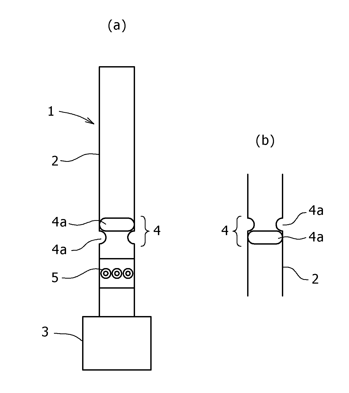
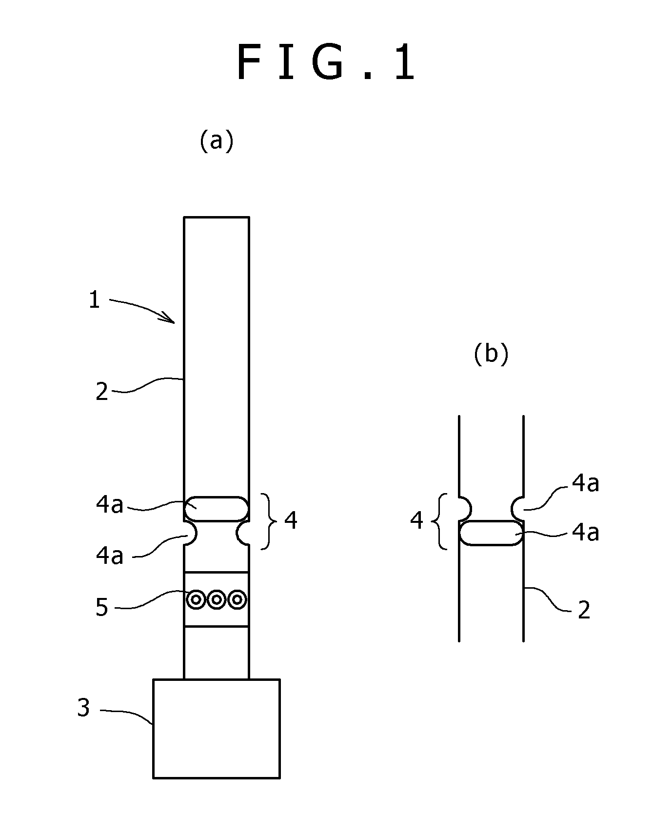
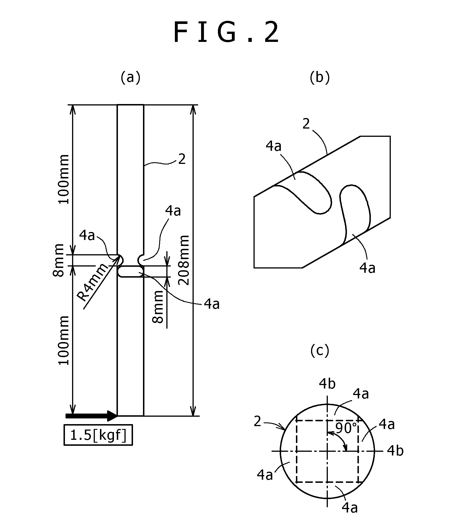
[0037]A deformation analysis was conducted using the models of the rotation support bar 2 shown in FIGS. 2(a)-(c) and FIGS. 3(a)-(c). The type shown in FIGS. 2(a)-(c) is the model provided with two pairs of grooves (four in total), and the type shown in FIGS. 3(a)-(c) is the model provided with three pairs of grooves (six in total).

[0038]Using the models of the rotation support bar of the grinding tool according to the present invention, the deformation analysis was conducted in such a manner that the upper end thereof is in a fixed state and a load of 1.5 kgf is applied to the l...


PUM


Abstract

The rotation support bar (2) of a grinding tool (1) has a bendable hinge section (4) at the intermediate section thereof, and has a balancer (5) on the grinding stone tip (3) side. The hinge section (4) comprises two or more opposed pairs of grooves (4a) which have circular arc-shaped bottom surfaces and which are provided in the outer peripheral surface of the rotation support bar (2) so as to extend in the direction perpendicular to the axial direction of the rotation support bar (2). The grooves (4a) are provided at equal angular intervals.

Description

TECHNICAL FIELD[0001]The present invention relates to a grinding tool for freely grinding the surface of metallic materials such as iron materials, aluminum material, or copper materials by a uniform grinding force.BACKGROUND ART[0002]In order to grind the surface of metallic materials such as iron materials, aluminum materials, or copper materials, grinding tools have been conventionally used. In grinding with the use of the conventional grinding tool, by moving the grinding tool with the use of a manually or numerically controlled (NC: Numerical Control) processing machine, grinding of the surface having a planar shape or a shape approximate to a plane could be performed without any hindrance. However, in case of grinding a curved surface or a nonuniform surface, grinding in a state that a positional relationship between a grinding stone tip provided at a leading end of the grinding tool and the surface of the metallic materials is uniform is difficult, so it was difficult to grin...

Claims


Application Information

Patent Timeline
Patent Type & Authority Applications(United States)
IPC IPC(8): B24B41/02
CPCB24B41/042B24D5/02B24D5/165B24B41/02
Inventor OZAKI, KATSUHIKO
Owner KOBE STEEL LTD
Why Eureka
Try Eureka