Rotary fluid machine

Inactive Publication Date: 2005-01-27
HONDA MOTOR CO LTD
View PDF4 Cites 7 Cited by
  • Summary
  • Abstract
  • Description
  • Claims
  • Application Information

AI Technical Summary

Benefits of technology

[0005] The present invention has been accomplished under the above-mentioned circumstances, and an object thereof is to lessen the influence of rotational runout of a rotor of a rotary fluid machine when a hollow rotating shaft provided integrally with the rotor is rotatably supported on the outer periphery of a fixed shaft fixed to a casing.
[0007] In accordance with this arrangement, since the fixed shaft is floatingly supported in the casing via the resilient support means having the alignment action, that is, it is connected with low rigidity and flexibly supported, and the hollow rotating shaft is supported on the outer periphery of the fixed shaft, when rotational runout of the rotor is transmitted to the fixed shaft via the rotating shaft, the rotational runout of the rotor can be suppressed by the alignment action of the resilient support means. The tracking ability of seal surfaces can thereby be improved, and the sealing characteristics can be enhanced by controlling the clearance with high precision, thus avoiding effectively any increase in the frictional resistance and any abnormal wear in a sliding section between the rotating shaft and the fixed shaft.
[0009] In accordance with this arrangement, since the rotary valve for controlling supplying and discharging of the high temperature gas-phase working medium is provided on the sliding surfaces of the rotating shaft and the fixed shaft, even when the outer peripheral face of the fixed shaft is worn due to a difference in thermal expansion between the fixed shaft and the rotating shaft, rotational runout of the rotor can be suppressed by the alignment action of the resilient support means, the amount of wear of the outer peripheral face of the fixed shaft thus becomes uniform, and it is therefore possible to precisely control the clearance between the sliding surfaces of the fixed shaft and the rotating shaft when they are hot. Moreover, once uniform contact when hot is formed by the initial setting of the rotary fluid machine, the sealing characteristics can always be maintained for subsequent introduction of the gas-phase working medium, and the sealing characteristics for the gas-phase working medium can be ensured by maintaining a small and uniform clearance.

Problems solved by technology

However, since it is impossible to avoid the occurrence of some degree of runout in the rotating rotor, if the above clearance is set so as to be small, the frictional resistance between the sliding surfaces of the fixed shaft and the rotating shaft is higher, and there is the problem of interference with the rotation of the rotor.
Furthermore, if the clearance between the sliding surfaces of the fixed shaft and the rotating shaft is set so as to be appropriate when they are cold, the outer peripheral face of the fixed shaft is worn due to a difference in thermal expansion in the vicinity of the rotary valve where the high temperature gas-phase working medium passes through, and since contact with the outer peripheral face of the fixed shaft is uneven due to rotational runout of the rotor, resulting in eccentric wear, there are the problems of a degradation in the sealing characteristics for the gas-phase working medium, an increase in the sliding resistance, and degradation of the rotational behavior of the rotor.

Method used


Image

  • Rotary fluid machine
  • Rotary fluid machine
  • Rotary fluid machine

Examples


first embodiment

[0012] the present invention is explained below with reference to FIG. 1 to FIG. 21D.

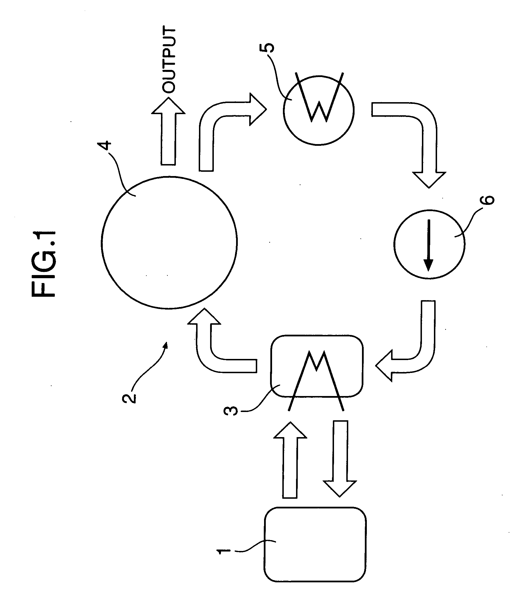
[0013] In FIG. 1, a waste heat recovery system 2 for an internal combustion engine 1 includes an evaporator 3 that generates high temperature, high pressure steam by vaporizing a high pressure liquid (e.g. water) using as a heat source the waste heat (e.g. exhaust gas) of the internal combustion engine 1, an expander 4 that generates an output by expansion of the steam, a condenser 5 that liquefies steam having decreased temperature and pressure as a result of conversion of the pressure energy into mechanical energy in the expander 4, and a supply pump 6 that pressurizes the liquid (e.g. water) from the condenser 5 and resupplies it to the evaporator 3.

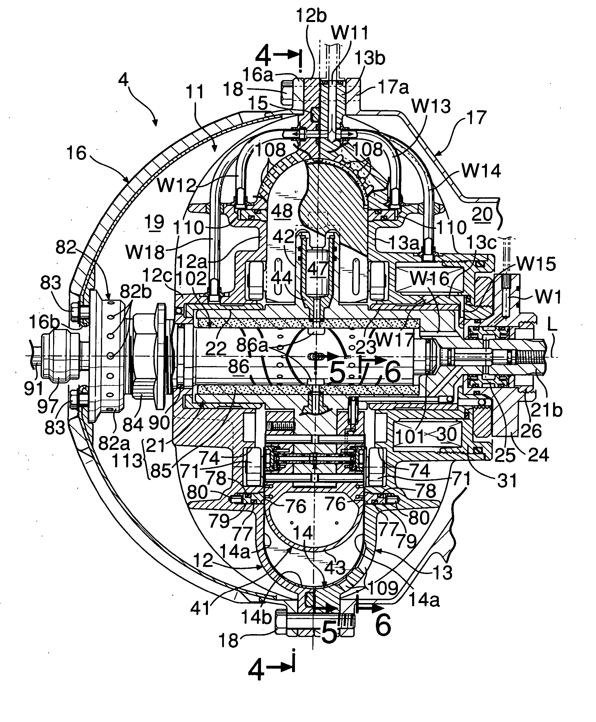
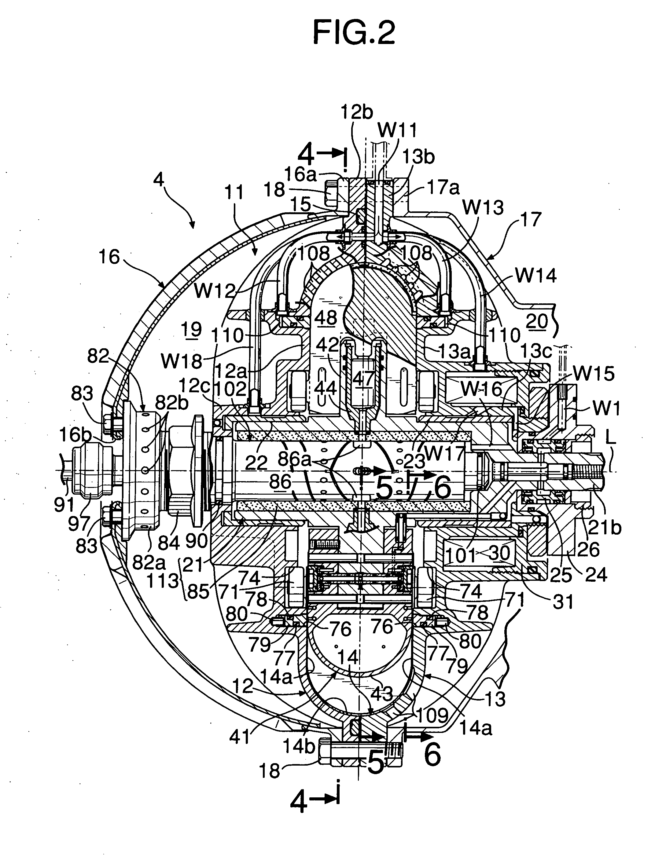
[0014] As shown in FIG. 2 and FIG. 3, a casing 11 of the expander 4 is formed from first and second casing halves 12 and 13, which are made of metal. The first and second casing halves 12 and 13 are formed from main body portions 12a and 13a, which i...

second embodiment

[0082] In the second embodiment, a second fixed shaft 93 extends leftward so as to cover the outer periphery of a steam supply pipe 91, and the left-hand end of the second fixed shaft 93 is fitted in and fixed to a boss portion 81a of a spring support member 81. A plurality (eight in this embodiment) of slits 93b extending in the axis L direction are formed in the second fixed shaft 93 adjacent to the boss portion 81a of the spring support member 81, and the section where these slits 93b are formed functions as a fixed shaft support spring 95. The fixed shaft support spring 95 can easily be elastically deformed in the radial direction by virtue of the slits 93b and, moreover, it can withstand a load in the axis L direction without being deformed.

[0083] In order to prevent steam that has leaked from the section where the right-hand end of the steam supply pipe 91 and the left-hand end of the first fixed shaft 92 are fitted together from passing through the slits 93b of the fixed shaf...


PUM


Abstract

A rotary fluid machine is provided that includes a rotor rotatably housed within a casing, a hollow rotating shaft (113) that rotates integrally with the rotor, and a fixed shaft (102) that is relatively rotatably fitted into the inner periphery of the rotating shaft (113); wherein the fixed shaft (102) is floatingly supported in the casing via a fixed shaft support spring (95) having an alignment action. When rotational runout of the rotor is transmitted to the fixed shaft (102) via the rotating shaft (113), the alignment action of the fixed shaft support spring (95) suppresses the rotational runout of the rotor, and any increase in the frictional resistance in a sliding section between the rotating shaft (113) and the fixed shaft (102) and the occurrence of abnormal wear can be prevented effectively, and the leakage of steam from a rotary valve (V) provided on the sliding surfaces of the rotating shaft (113) and the fixed shaft (102) can be reduced.

Description

FIELD OF THE INVENTION [0001] The present invention relates to a rotary fluid machine for interconverting the pressure energy of a gas-phase working medium and the rotational energy of a rotor. BACKGROUND ART [0002] A rotary fluid machine disclosed in Japanese Patent Application Laid-open No. 2000-320543 is equipped with a vane piston unit in which a vane and a piston are combined; the piston, which is slidably fitted in a cylinder provided radially in a rotor, interconverts the pressure energy of a gas-phase working medium and the rotational energy of the rotor via a power conversion device comprising an annular channel and a roller, and the vane, which is radially and slidably supported in the rotor, interconverts the pressure energy of the gas-phase working medium and the rotational energy of the rotor. [0003] In such a rotary fluid machine, a rotary valve for supplying and discharging a high temperature gas-phase working medium is formed between the outer peripheral face of a fi...

Claims


Application Information

Patent Timeline
IPC IPC(8): F01L33/02F01B13/06F01C1/344F01C11/00F01C20/14F01C21/02F01C21/08F01C21/18F01K7/00F02B53/00F04B1/047F04B53/00F04B53/10F04C18/344
CPCF01B13/061F01B13/068F01C1/3446F01C11/006F01C21/08F04C2240/605F02B53/00F04B1/047F04C2230/602F04C2240/601F01C21/18
Inventor ICHIKAWA, HIROSHIENDOH, TSUNEOTAKAHASHI, TSUTOMUKIMURA, YASUNARI
Owner HONDA MOTOR CO LTD
Why Eureka
Try Eureka