Fuel injection valve

Inactive Publication Date: 2006-12-21
DENSO CORP
View PDF5 Cites 7 Cited by
  • Summary
  • Abstract
  • Description
  • Claims
  • Application Information

AI Technical Summary

Benefits of technology

[0008] It is another object of the present invention to provide a fuel injection valve which, even when influenced by an intra-cylinder pressure of an internal combustion engine, can diminish the driving force of an electromagnetic drive section for opening the valve and can keep a valve member closed.
[0010] According to this construction, it is possible to lessen the influence of fuel pressure acting on the valve element in the valve closing direction and hence possible to diminish the driving force of the electromagnetic drive section for opening the valve.

Problems solved by technology

However, in case of injecting fuel directly into a combustion chamber from a fuel injection valve, the needle is urged with a large force in the valve closing direction because of a high fuel pressure for direct injection.

Method used


Image

  • Fuel injection valve
  • Fuel injection valve
  • Fuel injection valve

Examples


first embodiment

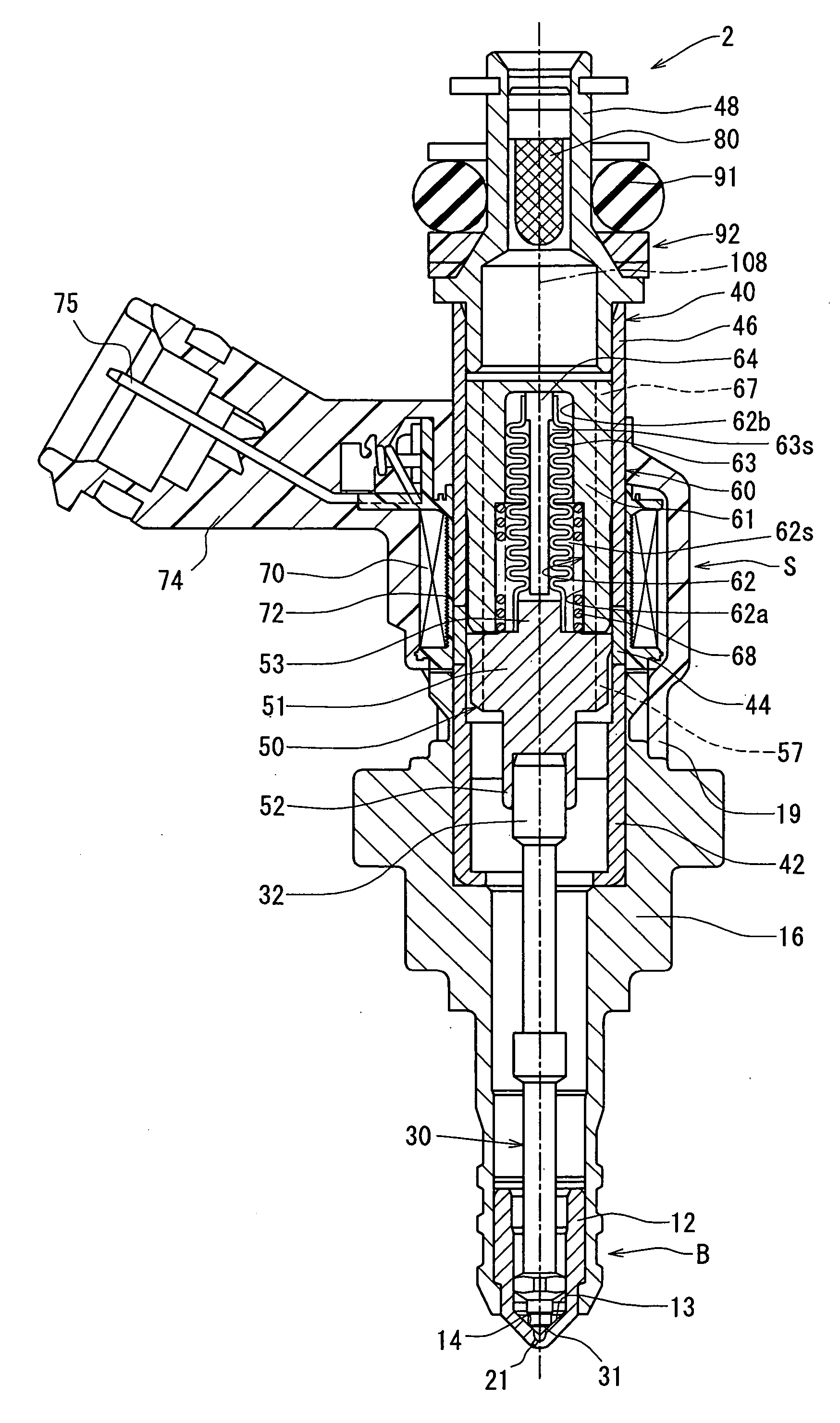
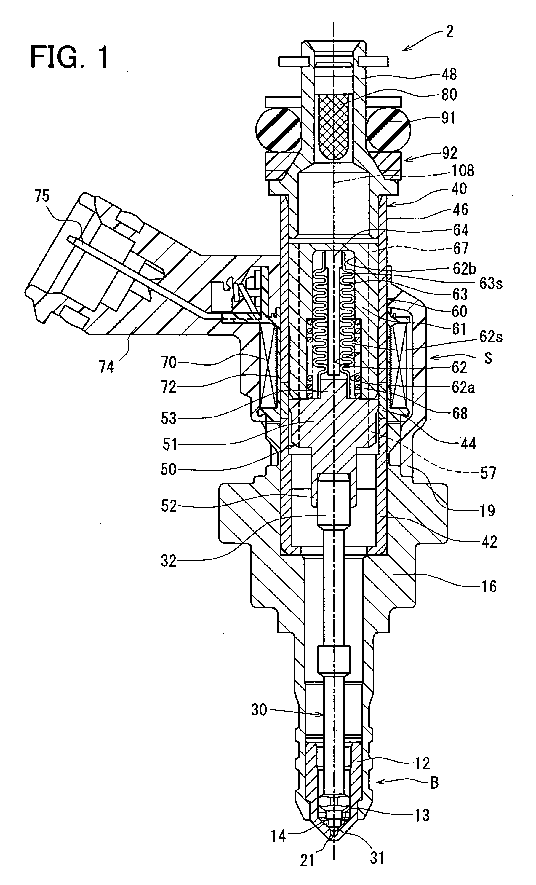
[0021]FIG. 1 is a sectional view showing the construction of a fuel injection valve according to a first embodiment of the present invention. FIG. 1 shows a state in which the fuel injection valve is closed and an electromagnetic drive section is not in operation.

[0022] As shown in FIG. 1, the fuel injection valve 2 is used in an internal combustion engine, especially a gasoline engine. The fuel injection valve 2 is mounted to for example an intake pipe or each cylinder in a multi-cylinder (e.g., four-cylinder) gasoline engine (hereinafter referred to simply as “engine”) to inject fuel into a combustion chamber formed in each cylinder. In this embodiment it is assumed that the fuel injection valve 2 is provided in each cylinder. Fuel pressurized by a fuel pump (not shown) is fed to the fuel injection valve 2 through a fuel distribution pipe (not shown). Generally, fuel present within a fuel tank (not shown) is pumped up and discharged by a fuel pump (not shown) and is then conducte...

second embodiment

[0080] Another embodiment of the present invention will be described below. In the following embodiment, constituent portions same as or equal to those described in the first embodiment are identified by the same reference numerals as in the first embodiment, and explanations thereof will be omitted.

[0081] The first embodiment is constructed such that the urging force for urging the valve elements 30 and 50 in the closing direction can be obtained by the load on the spring 68 and that of the tubular receptacle 63. On the other hand, in this second embodiment, as shown in FIG. 4, the said urging force is obtained by the load on the tubular receptacle 63. FIG. 4 is a partial sectional view showing an electromagnetic drive section and the vicinity thereof related to this embodiment.

[0082] As shown in FIG. 4, a receptacle hole 162 is formed inside the magnetic pole face 65 of the fixed core 60. The receptacle hole 162 is formed with an inner periphery 162b for accommodating the tubula...

third embodiment

[0090] In a third embodiment of the present invention, as shown in FIG. 5, the valve element described in the first embodiment is modified so as to have inner peripheries 134 and 154 which permit insertion of a support member 164 toward the valve seat 14, and an opening of the inner periphery 134 located on the valve seat 14 side is positioned inside the valve seat 14. FIG. 5 is a sectional view showing the construction of a fuel injection valve according to this third embodiment. FIG. 6 is a partial sectional view of an electromagnetic drive section and the vicinity thereof shown in FIG. 5. FIG. 7 is a partial sectional view of the valve element and a valve body both shown in FIG. 5.

[0091] As shown in FIG. 5, the valve element is made up of a movable core 150 and a needle 130. The movable core 150 has a cylindrical portion 151, a holding portion 152, a support portion 153, and an inner periphery 154 extending axially through the interior of the movable core 150. The needle 130 has...


PUM


Abstract

A fuel injection valve includes a valve body having a valve seat, a valve element adapted to sit on and leave a valve seat, a nozzle hole for the injection of fuel, and an electromagnetic drive section. A holding member surrounds and holds, on one end side thereof, at least a partial area of an opposite-to-nozzle-hole-side end face portion of the valve element. The holding member surrounds and holds, on an opposite end side thereof, a predetermined surface area of a constant position holding portion without being influenced by the pressure of fuel flowing through a fuel passage of the valve body and irrespective of movement of the valve element. An internal area of the holding member is shut off so as not to be influenced by the pressure of fuel present around the internal area.

Description

CROSS-REFERENCE TO RELATED APPLICATION [0001] This application is based on Japanese patent Applications No. 2005-171509 filed on Jun. 10, 2005, and No. 2006-64535 filed on Mar. 9, 2006, the disclosure of which are incorporated herein by reference. FIELD OF THE INVENTION [0002] The present invention relates to a fuel injection valve, which supplies fuel by injection into an internal combustion engine. BACKGROUND OF THE INVENTION [0003] JP-9-14090A and JP-2002-310030A show a fuel injection valve having an electromagnetic solenoid which magnetically attracts a movable core connected to a valve needle and adapted to cooperate with the valve needle, thereby driving the valve needle directly. The valve needle is adapted to sit on and leave a valve seat. The fuel injection valve of this type is provided with an elastic member such as a spring for urging the valve needle toward the valve seat. The movable core is provided at an end of the valve needle on the side opposite to the valve seat,...

Claims


Application Information

Patent Timeline
IPC IPC(8): B05B1/30
CPCF02M51/061F02M61/20F02M51/0678
Inventor MOCHIZUKI, KOUICHISAITO, KIMITAKANAGATOMO, HIROAKI
Owner DENSO CORP
Why Eureka
Try Eureka