Electric vehicle

a technology for electric vehicles and vehicles, applied in the direction of electric devices, vehicle sub-unit features, battery/fuel cell control arrangement, etc., can solve the problem of low degree of freedom in arranging devices, and achieve the effect of enhancing the degree of freedom in laying out devices in front compartments, reducing the fixation strength of inner sides, and reducing impa

Active Publication Date: 2015-12-31
TOYOTA JIDOSHA KK
View PDF19 Cites 11 Cited by
  • Summary
  • Abstract
  • Description
  • Claims
  • Application Information

AI Technical Summary

Benefits of technology

[0008]As described above, the degree of freedom in laying out the devices in the front compartment can be enhanced by arranging the inverter outside the two frame members (outside in the vehicle width direction). Besides, the inner side of the inverter is fixed to one of the frame members, and the outer side of the inverter is fixed to the cabin outer plate. Also, the fixation strength of the inner side is made lower than the fixation strength of the outer side. Thus, upon receiving an impact diagonally from in front of the vehicle, the inverter is freed from the frame member, but remains coupled to the cabin outer plate. The inverter is allowed to move to a moderate degree, so the impact can be mitigated.
[0009]In the aforementioned structure, the inner side of the inverter in the vehicle width direction is fixed to one of the frame members. The advantage of the structure can also be obtained from the following structure. That is, both the inner and outer sides of the inverter in the vehicle width direction are fixed to the cabin outer plate, and the cabin outer plate is fixed to one of the frame members inside the inverter in the vehicle width direction. Then, the fixation strength of the outer side of the inverter in the vehicle width direction is made higher than the fixation strength of the inner side of the inverter in the vehicle width direction or the fixation strength between the cabin outer plate and the frame member. In such a structure as well, upon receiving an impact diagonally from in front of the vehicle, the inverter is freed from the frame member, but remains coupled to the cabin outer plate. The inverter is allowed to move to a moderate degree, so the impact can be mitigated.

Problems solved by technology

In this case, however, the degree of freedom in arranging the devices is low.

Method used


Image

  • Electric vehicle
  • Electric vehicle
  • Electric vehicle

Examples


embodiments

[0023](First Embodiment)

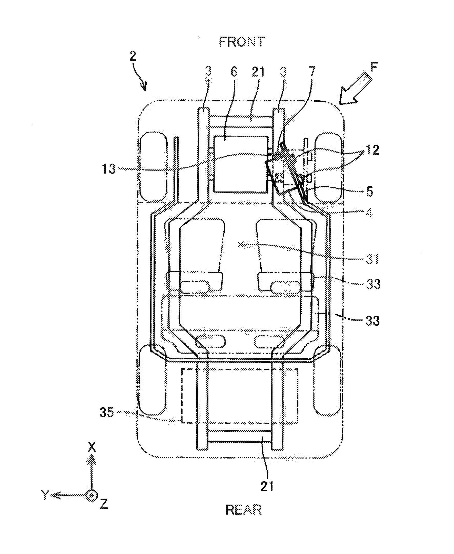
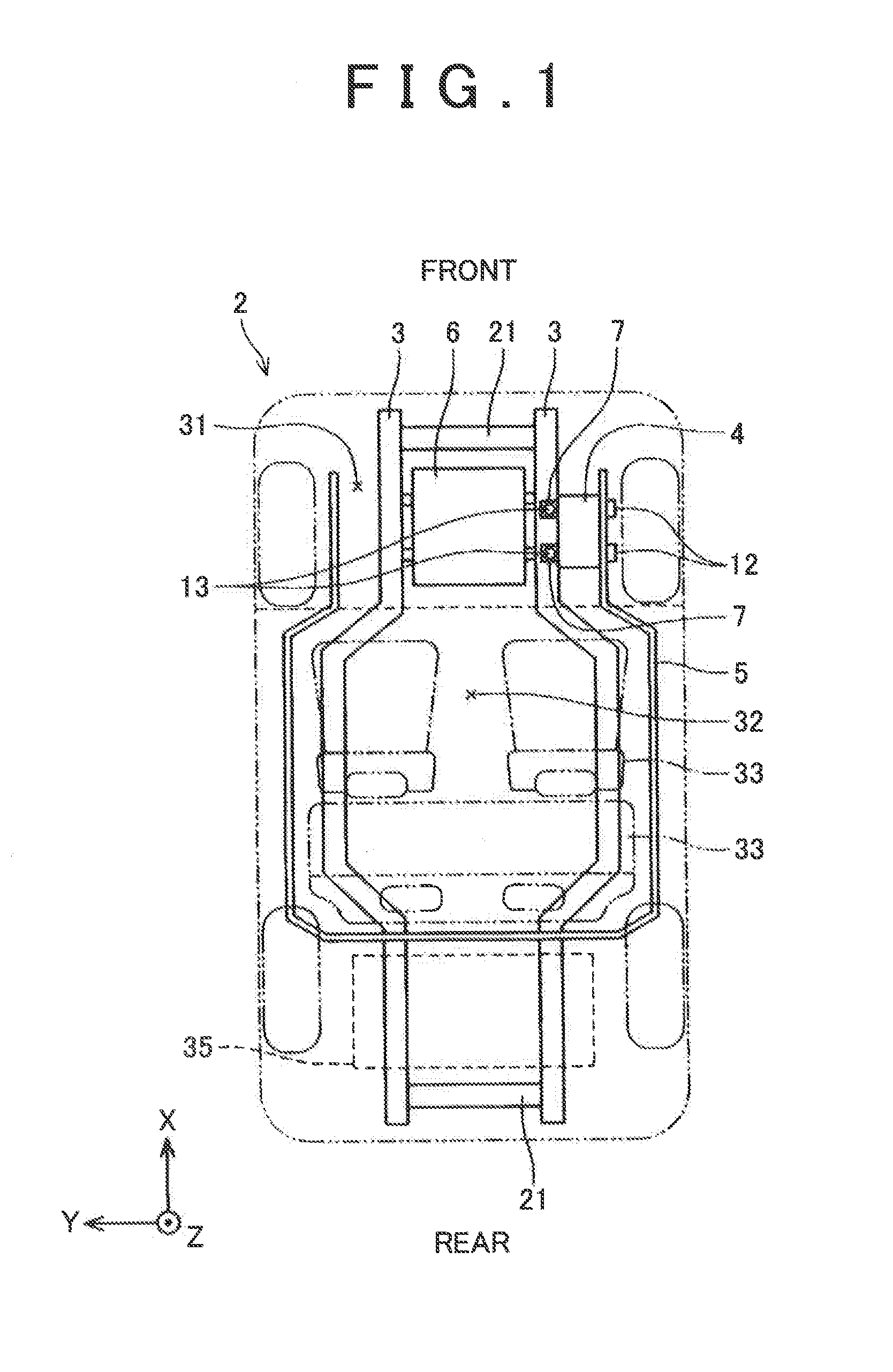
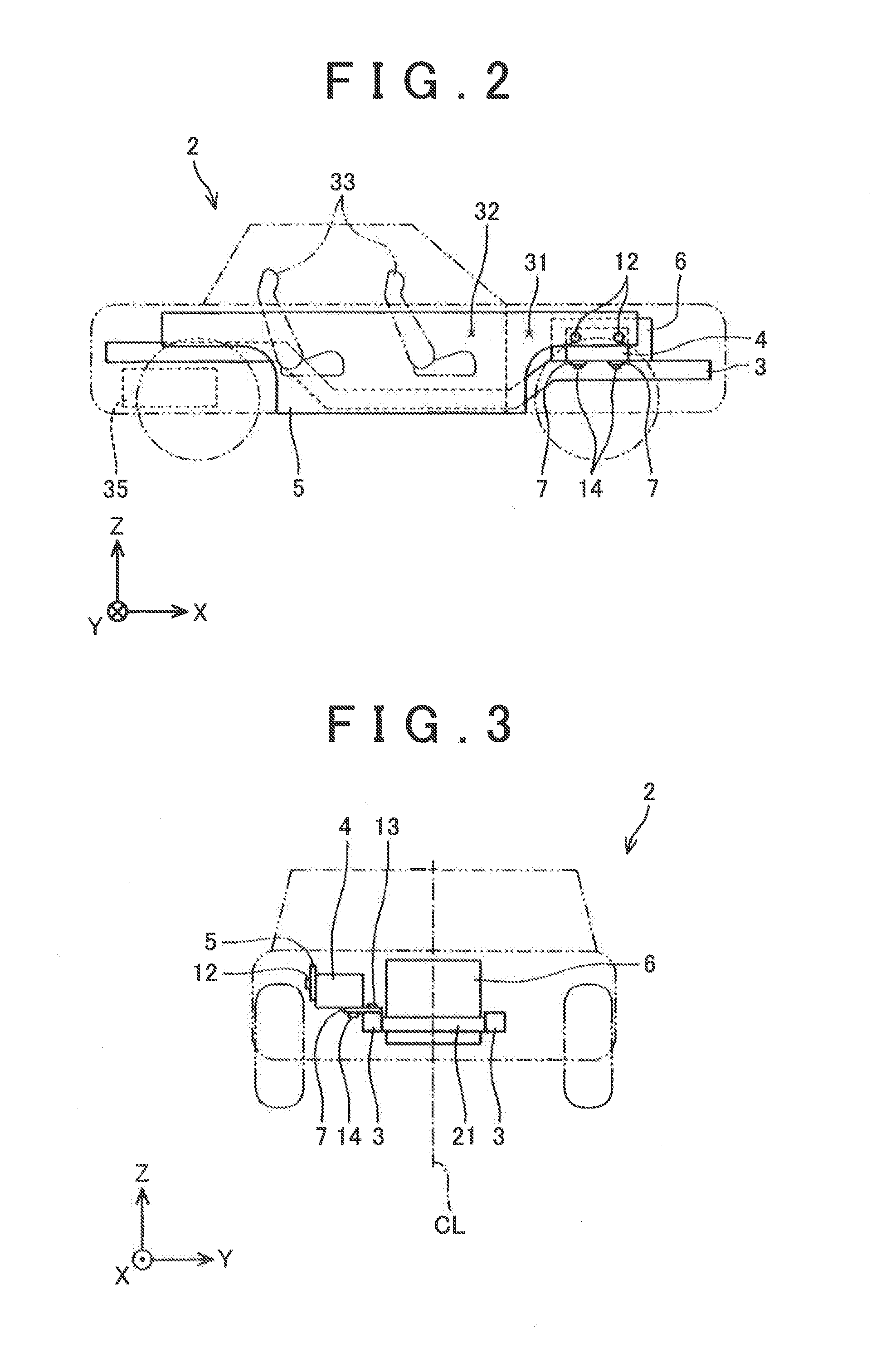
[0024]FIGS. 1 to 3 are plan, lateral and front views showing the electric vehicle according to the first embodiment of the invention, respectively. Incidentally, a relationship among frame members of the vehicle, a cabin outer plate, and the inverter will be described herein, so the diagrammatic representation and description of other components will be arbitrarily omitted.

[0025]A front compartment 31 of an electric vehicle 2 is mounted with a traction motor 6 and an inverter 4. The inverter 4 converts a direct-current electric power of a battery 35, which is arranged in a luggage space in a rear part of the vehicle, into an alternating-current electric power, and supplies this alternating-current electric power to the motor 6. A large alternating current is supplied from the inverter 4 to the motor 6, so the inverter 4 is arranged close to the motor 6 with a view to reducing the transmission loss in electric power. Therefore, both the motor 6 and the inverte...


PUM


Abstract

An electric vehicle disclosed by the present specification, includes an inverter arranged outside frame members in a vehicle width direction, in a front compartment. An inner side of the inverter in the vehicle width direction is fixed to one of the frame members. An outer side of the inverter in the vehicle width direction is fixed to a cabin outer plate. Furthermore, a fixation strength of the inner side of the inverter is lower than a fixation strength of the outer side of the inverter.

Description

CROSS-REFERENCE TO RELATED APPLICATIONS[0001]This application is a national phase application of International Application No. PCT / JP2013 / 054139, filed Feb. 20, 2013, the content of which is incorporated herein by reference.TECHNICAL FIELD[0002]The invention relates to an electric vehicle. In particular, the invention relates to a mounting structure of an inverter that converts a direct-current electric power of a battery into an alternating-current electric power and that supplies this alternating-current electric power to a motor in an electric vehicle. “The electric vehicle” in the present specification includes a fuel-cell vehicle and a hybrid vehicle equipped with an engine as well as a motor.BACKGROUND ART[0003]There are two types of vehicle body structures, that is, a monocoque structure and a frame structure. The monocoque structure imparts a structural strength by a plate material. The frame structure imparts a structural strength by a frame as a combination of beams. A mot...

Claims


Application Information

Patent Timeline
Patent Type & Authority Applications(United States)
IPC IPC(8): B60L3/00B62D21/15B60K1/00
CPCB60K1/00B62D21/152B60L58/30B60K2001/0416B60K2001/0438B60Y2306/01B60Y2400/61B60L3/0007B60L2210/40Y02T10/705Y02T10/7241Y02T90/34B62D21/157B60L3/0015B60L3/003Y02T10/645B60L15/007B60L50/66Y02T10/64Y02T10/70Y02T10/72Y02T90/40
Inventor YAMANAKA, KENSHI
Owner TOYOTA JIDOSHA KK
Why Eureka
Try Eureka