Eureka AIR delivers breakthrough ideas for toughest innovation challenges, trusted by R&D personnel around the world.

Controller and map file conversion device

a control device and map file technology, applied in the field of control techniques of drive devices, can solve the problems of difficult to determine which data, testers to analogize function codes, poor operation efficiency during maintenance and inspection, etc., and achieve the effect of increasing the efficiency of maintenance and inspection operations, easy intuitive recognition, and flexible adaptation

Active Publication Date: 2015-12-31
FUJI ELECTRIC CO LTD
View PDF10 Cites 3 Cited by
  • Summary
  • Abstract
  • Description
  • Claims
  • Application Information

AI Technical Summary

Benefits of technology

The present invention provides a technique to read and update data without applying a processing load to the drive device. It allows for flexible adaptation to additional, modifications, and deletion of data. The controller uses a symbol name to specify which data is to be read or updated, and the conversion from symbol to address is performed at the controller side, without adding extra load on the drive device. This results in improved efficiency and flexibility for maintenance and inspection operations.

Problems solved by technology

However, the following problems are associated with the specification of data by the function codes.
Firstly, the operation efficiency during maintenance and inspection is poor.
Since a function code is mostly assigned as a sequential number, it is difficult to determine which data are represented from the function code, and it is also difficult to cause the tester to analogize the function codes of data which are wished to be read or updated.
Secondly, each time the data which are the object of reading or updating are appended, modified, and deleted, the table stored in each drive device needs to be updated.
Thirdly, an extra processing load is placed on the drive device which is the object of maintenance and inspection due the conversion of the function code to the address, and it is possible that accurate inspection would not be performed.

Method used


Image

  • Controller and map file conversion device
  • Controller and map file conversion device
  • Controller and map file conversion device

Examples


Embodiment Construction

[0022]An embodiment of the present invention will be described hereinbelow with reference to the drawings.

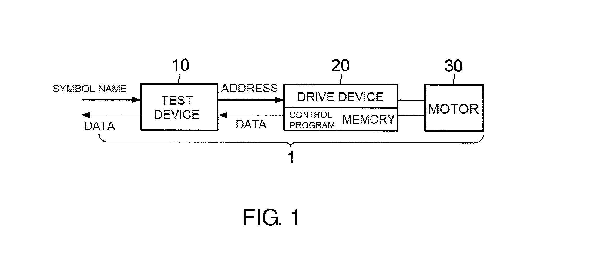
[0023]FIG. 1 illustrates a configuration example of a test system 1 including a test device 10 of one embodiment of the controller in accordance with the present invention. The test system 1 serves for maintaining and inspecting a drive device 20 which is installed together with a motor 30 on an electric automobile. As depicted in FIG. 1, the test system 1 includes the drive device 20 which is the object of maintenance and inspection, the motor 30 which is drive-controlled by the drive device 20, and the test device 10 which plays the role of a controller that controls the drive device 20 while the maintenance and inspection are executed.

[0024]The motor 30 may be a three-phase AC motor. The drive device 20 is an inverter that converts DC power supply, for example from an onboard battery, into three-phase AC power and supplies the converted power to the motor 30. The drive device...


PUM


Abstract

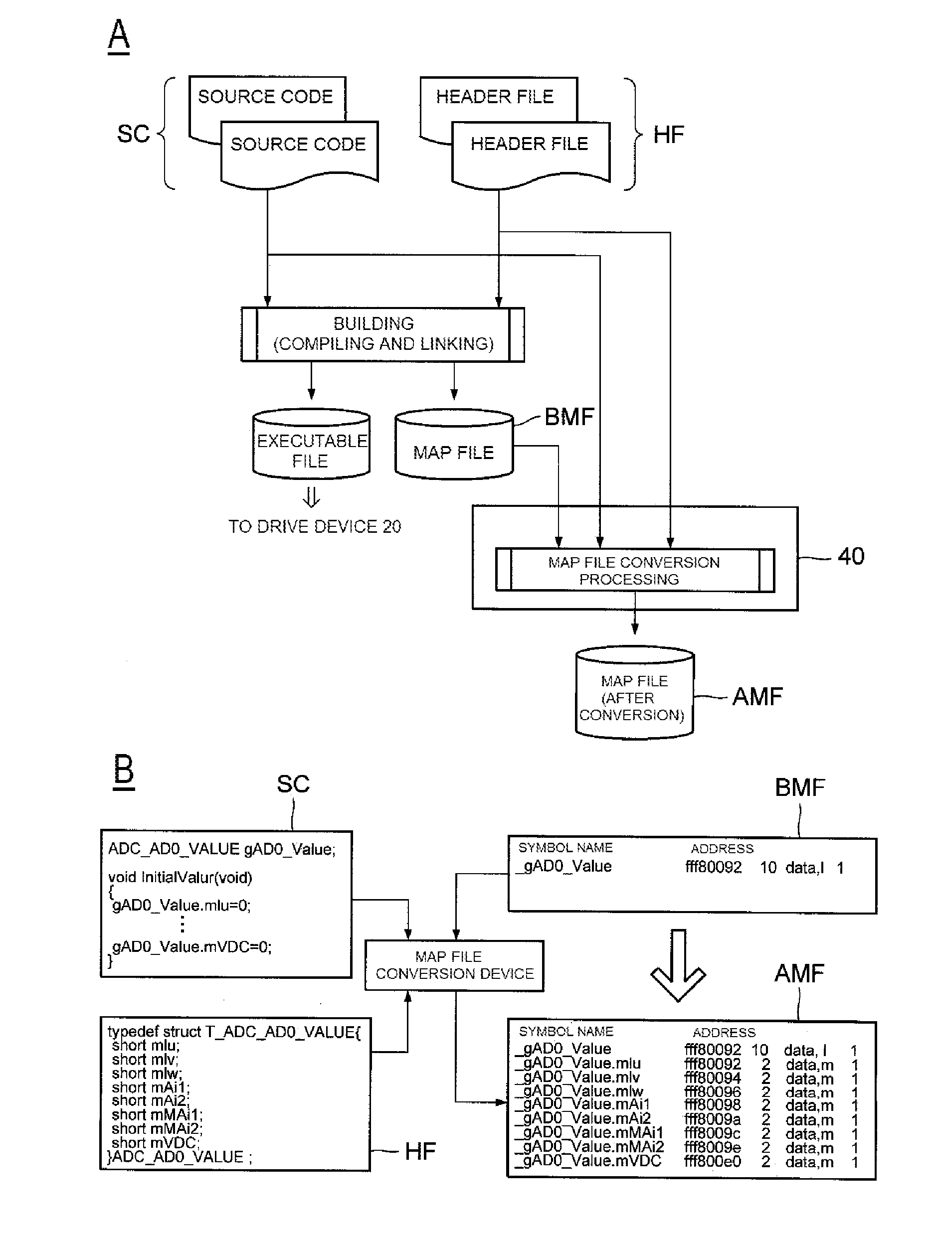
A controller for controlling a drive device that executes drive control of a motor. The controller includes a processing device and a memory having program instructions stored thereon. Execution of the program instructions by the processing device causes the controller to obtain a symbol name provided to indicate data that are an object of reading or updating, to convert the obtained symbol name into an address with reference to a map file, where the map file uses each symbol name included in a source code of a control program as an identifier of the data corresponding to each symbol name, and associates each symbol name with an address of a storage area storing the corresponding data, and to instruct the drive device to read or update the data stored in the storage area indicated by the address obtained through the conversion.

Description

CROSS-REFERENCE TO RELATED APPLICATIONS[0001]This application is a continuation application under 35 U.S.C. 120 of International Application PCT / JP2014 / 059723 having the International Filing Date of Apr. 2, 2014, and claims the priority of Japanese Patent Application No. JP PA 2013-095383, filed on Apr. 30, 2013. The identified applications are fully incorporated herein by reference.BACKGROUND OF THE INVENTION[0002]1. Technical Field[0003]The invention relates to a control technique for a drive device that performs drive control of a motor by controlling the power supplied to the motor.[0004]2. Background Art[0005]As the interest in environmental issues has been growing in recent years, battery-powered electric automobiles using an onboard battery as a power source (referred to hereinbelow simply as “electric automobiles”) have attracted attention. In an electric automobile, a motor such as a three-phase AC motor is installed as a power source. Also installed are a drive device, suc...

Claims


Application Information

Patent Timeline
IPC IPC(8): B60L3/12G06F17/30B60L15/20H02P29/00
CPCB60L3/12B60L2240/421B60L2240/423B60L2250/12B60L2250/16G06F9/44521Y02T10/7258Y02T10/642G06F16/116G06F9/45516B60L15/20Y02T10/64Y02T10/72
Inventor SAWADA, TAKAO
Owner FUJI ELECTRIC CO LTD
Why Eureka
Eureka Blog
Learn More