Multi-Mode Filter Having Aperture Arrangement with Coupling Segments

a filter and aperture arrangement technology, applied in the field of filters, can solve the problems of large size of filter equipment, unsuitable implementation, complicated body shape, etc., and achieve the effect of precise tailoring of filter frequency response characteristics and increasing manufacturing costs

Inactive Publication Date: 2015-12-31
MESAPLEXX
View PDF2 Cites 6 Cited by
  • Summary
  • Abstract
  • Description
  • Claims
  • Application Information

AI Technical Summary

Benefits of technology

[0011]It is an advantage of the present invention that it provides a means to allow careful control of the degree of coupling achieved to multiple modes, excited simultaneously, in a multi-mode filter and thereby to allow the precise tailoring of a filter's frequency response characteristic, by means of the design of the coupling structure or structures alone, without any need for a complex shape of multi-mode resonator, nor the need for defects to be applied to a simpler shape of multi-mode resonator.
[0012]An alternative manner in which these multi-mode filters may be implemented is to couple the energy from an input port, simultaneously to each one of the modes, by means of a suitably designed coupling track. Again, in this manner, a multi-mode filter can be implemented as an effective cascade of resonators, in a similar way to conventional single mode filter implementations. As was the case above, in which defects were used to enable multiple modes to be excited in a single resonator, this technique results in transmission poles which can be tuned to provide a desired filter response. This type of filter has been disclosed in various US patent filings, for example: U.S. Ser. No. 13 / 488,123, U.S. Ser. No. 13 / 488,059, U.S. Ser. No. 13 / 487,906 and U.S. Ser. No. 13 / 488,182.
[0013]Two or more triple-mode filters may still need to be cascaded together to provide a filter assembly with suitable filtering characteristics. As described in U.S. Pat. Nos. 6,853,271 and 7,042,314 this may be achieved using a single waveguide or a centrally-located single aperture for providing coupling between two resonator mono-bodies. With this approach, the precise control of the modes being coupled to, coupled from or coupled between the bodies, is difficult to achieve and thus, as a consequence, achieving a given, challenging, filter specification is difficult.
[0014]Another approach includes using a single-mode combine resonator coupled between two dielectric mono-bodies to form a hybrid filter assembly as described in U.S. Pat. No. 6,954,122. In this case, the physical complexity and hence manufacturing costs are even further increased, over and above the use of added defects alone.
[0015]According to an aspect of the present invention, there is provided a multi-mode cavity filter, comprising: at least one dielectric resonator body incorporating a piece of dielectric material, the piece of dielectric material having a shape such that it can support at least a first resonant mode and at least a second substantially degenerate resonant mode; a layer of conductive material in contact with and covering the dielectric resonator body; at least one aperture in the layer of conductive material comprising at least a first coupling segment and a second coupling segment the first coupling segment being arranged to couple at least one of a first magnetic field and a first electric field to at least one of the first resonant mode and the second resonant mode within the dielectric resonator body, the second coupling segment being arranged to couple at least one of a second magnetic field and a second electric field to at least one of the first resonant mode and the second resonant mode within the dielectric resonator body; wherein at least one of the second magnetic field and the second electric field has a magnitude and a direction so as to partially cancel the coupling due to at least one of the first magnetic field and the first electric field.
[0016]The at least one aperture may, for example, comprise at least one of an input coupling aperture and an output coupling aperture for respectively coupling signals to and from the dielectric resonator body.

Problems solved by technology

A number of resonators will usually be required to achieve suitable filtering characteristics for commercial applications, resulting in filtering equipment of a relatively large size.
However, the size of single mode filters as described above can make these undesirable for implementation at the top of antenna towers.
However, the approach used to couple energy into and out of the resonator, and between the modes within the resonator to provide the effective resonator cascade, requires the body to be of complicated shape, increasing manufacturing costs.
With this approach, the precise control of the modes being coupled to, coupled from or coupled between the bodies, is difficult to achieve and thus, as a consequence, achieving a given, challenging, filter specification is difficult.
In this case, the physical complexity and hence manufacturing costs are even further increased, over and above the use of added defects alone.

Method used


Image

  • Multi-Mode Filter Having Aperture Arrangement with Coupling Segments
  • Multi-Mode Filter Having Aperture Arrangement with Coupling Segments
  • Multi-Mode Filter Having Aperture Arrangement with Coupling Segments

Examples


Embodiment Construction

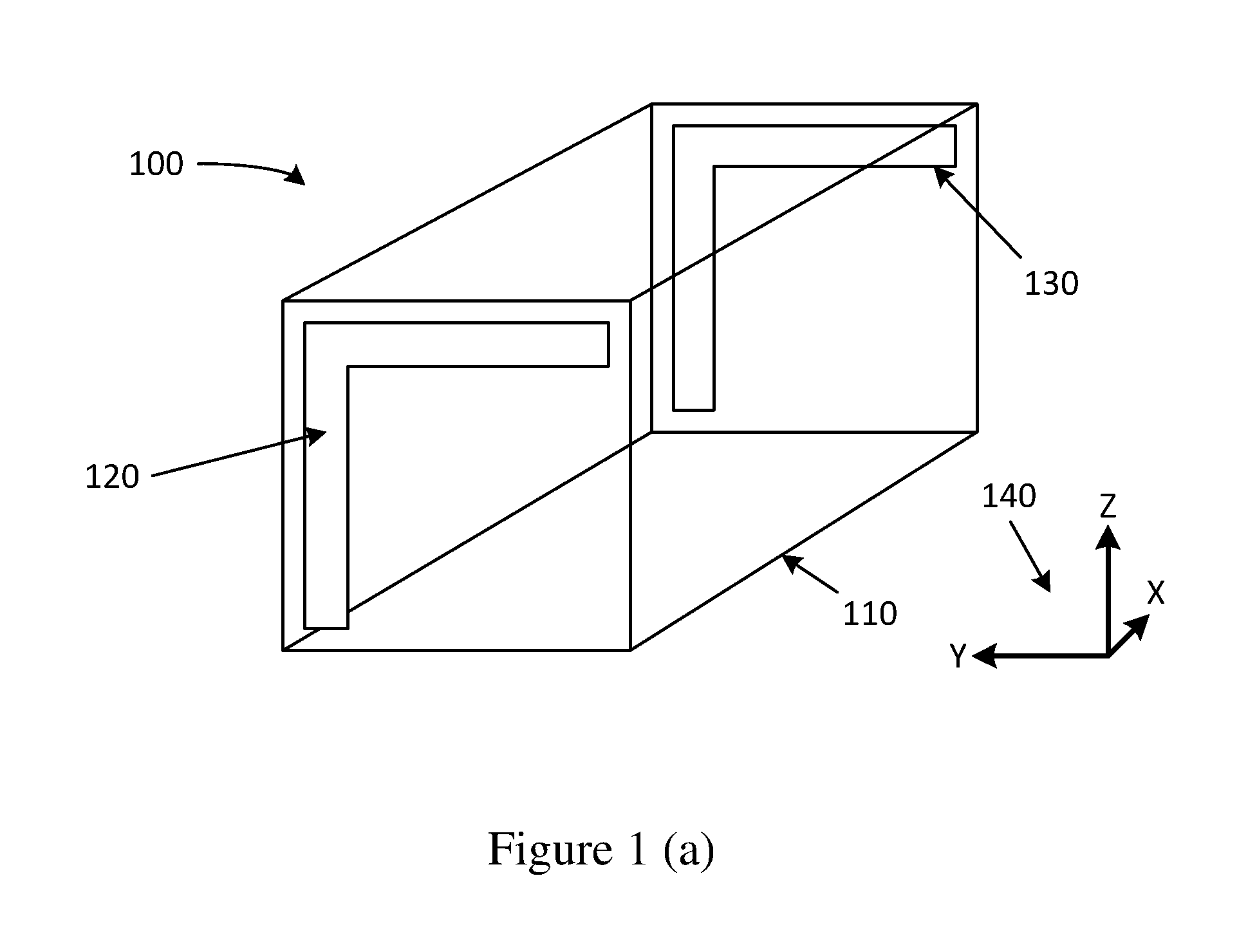
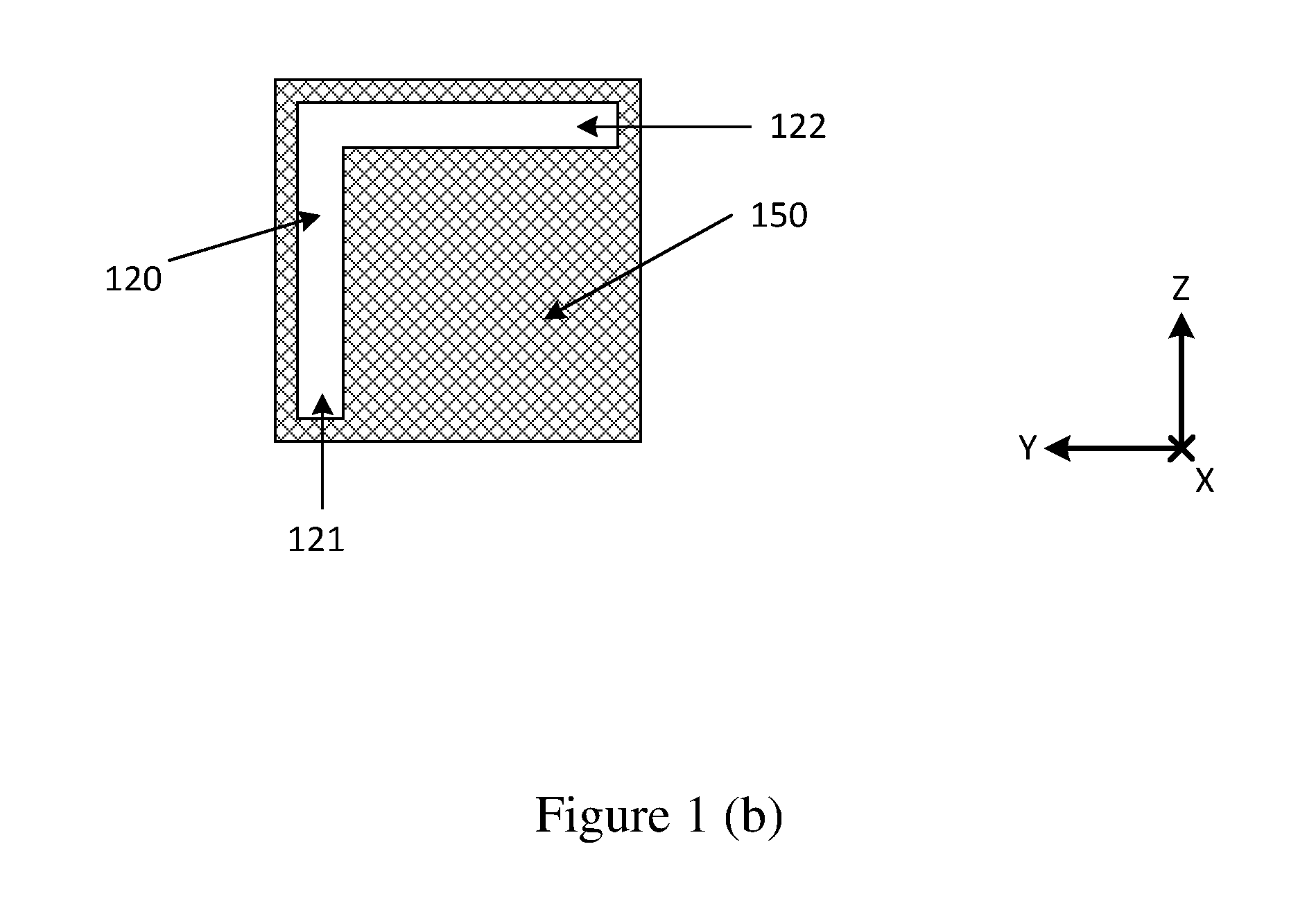
[0055]An example of a multi-mode filter will now be described with reference to FIGS. 1a and 1b.

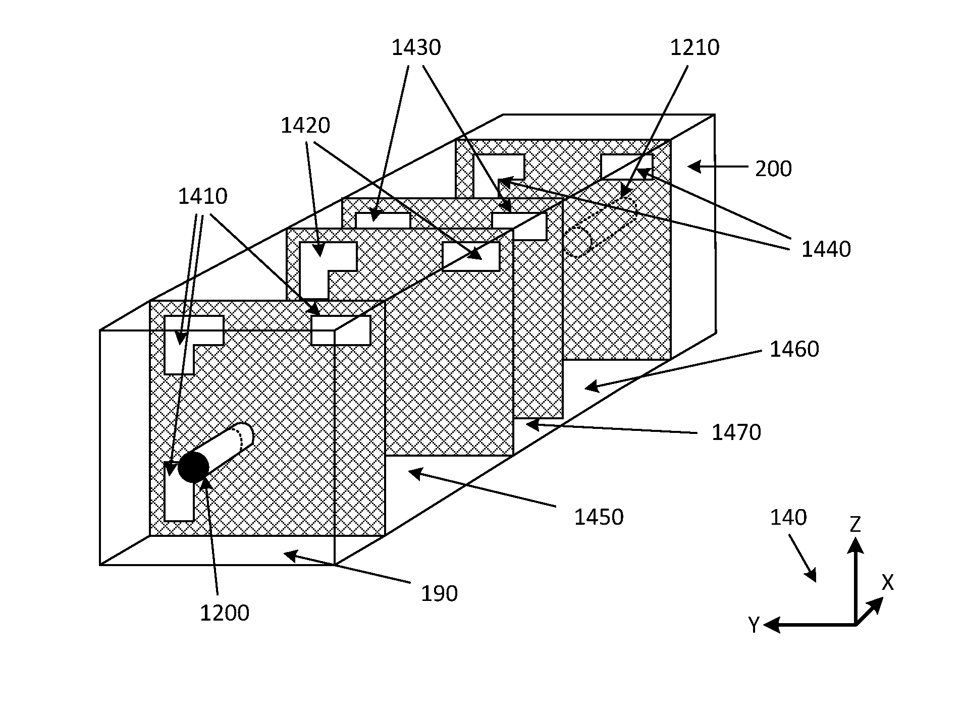
[0056]The basis of this invention is in the use of a specific type of coupling aperture arrangement to couple signals into and out of a multi-mode resonator, whilst exciting (or coupling energy from) two or more modes, simultaneously, within that resonator.

[0057]In this example, the filter 100 includes a resonator body 110 which is encapsulated in a metallised layer (which is not shown, for clarity). At least two aperture arrangements are formed in the metallised layer: an input coupling aperture 120 and an output coupling aperture 130. These apertures are constituted by an absence of metallisation, with the remainder of the resonator body being substantially encapsulated in its metallised layer. The apertures 120 and 130 may be formed by, for example, etching, either chemically or mechanically, the metallisation surrounding the resonator body, 110, to remove metallisation and thereby fo...


PUM


Abstract

A multi-mode filter including a resonator body including a piece of dielectric material, the resonator body being configured to support a first resonant mode and a second resonant mode, the resonator body having a covering of an electrically conductive material, wherein the covering is provided with a coupling aperture arrangement, the coupling aperture arrangement including a first coupling segment and a second coupling segment, wherein the first coupling segment is configured to couple a first magnetic field or a first electric field to the first resonant mode or the second resonant mode within the resonator body and the second coupling segment is configured to couple a second magnetic field or a second electric field to the first resonant mode or the second resonant mode within the resonator body.

Description

TECHNICAL FIELD[0001]The present invention relates to filters, and in particular to a multi-mode filter including a resonator body for use, for example, in frequency division duplexers for telecommunication applications.BACKGROUND[0002]The reference in this specification to any prior publication (or information derived from it), or to any matter which is known, is not, and should not be taken as an acknowledgment or admission or any form of suggestion that the prior publication (or information derived from it) or known matter forms part of the common general knowledge in the field of endeavour to which this specification relates.[0003]All physical filters essentially consist of a number of energy storing resonant structures, with paths for energy to flow between the various resonators and between the resonators and the input / output ports. The physical implementation of the resonators and the manner of their interconnections will vary from type to type, but the same basic concept app...

Claims


Application Information

Patent Timeline
Patent Type & Authority Applications(United States)
IPC IPC(8): H01P1/20H01P7/10
CPCH01P1/2082H01P7/06H01P7/105
Inventor COOPER, STEVEN JOHNHENDRY, DAVID ROBERTKENINGTON, PETER BLAKEBOROUGH
Owner MESAPLEXX
Why Eureka
Try Eureka