
Method for manufacturing a FBG having improved performances and an annealing-trimming apparatus for making the same

a technology of annealing and fbg, which is applied in the direction of electrical apparatus, cladded optical fibre, instruments, etc., can solve the problems of difficult to obtain ilef smaller than .+-.0.15 db, long manual uv-trimming process, and inability to achieve precise tailoring, etc., to achieve the effect of improving performance and precise tailoring

Active Publication Date: 2004-08-19
TERAXION
View PDF3 Cites 6 Cited by
  • Summary
  • Abstract
  • Description
  • Claims
  • Application Information

AI Technical Summary

Benefits of technology

[0006] It is therefore an object of the present invention to provide a method and apparatus allowing a more precise tailoring of the characteristic spectra of a FBG than for prior art manufacturing techniques, thereby providing a FBG having improved performances.
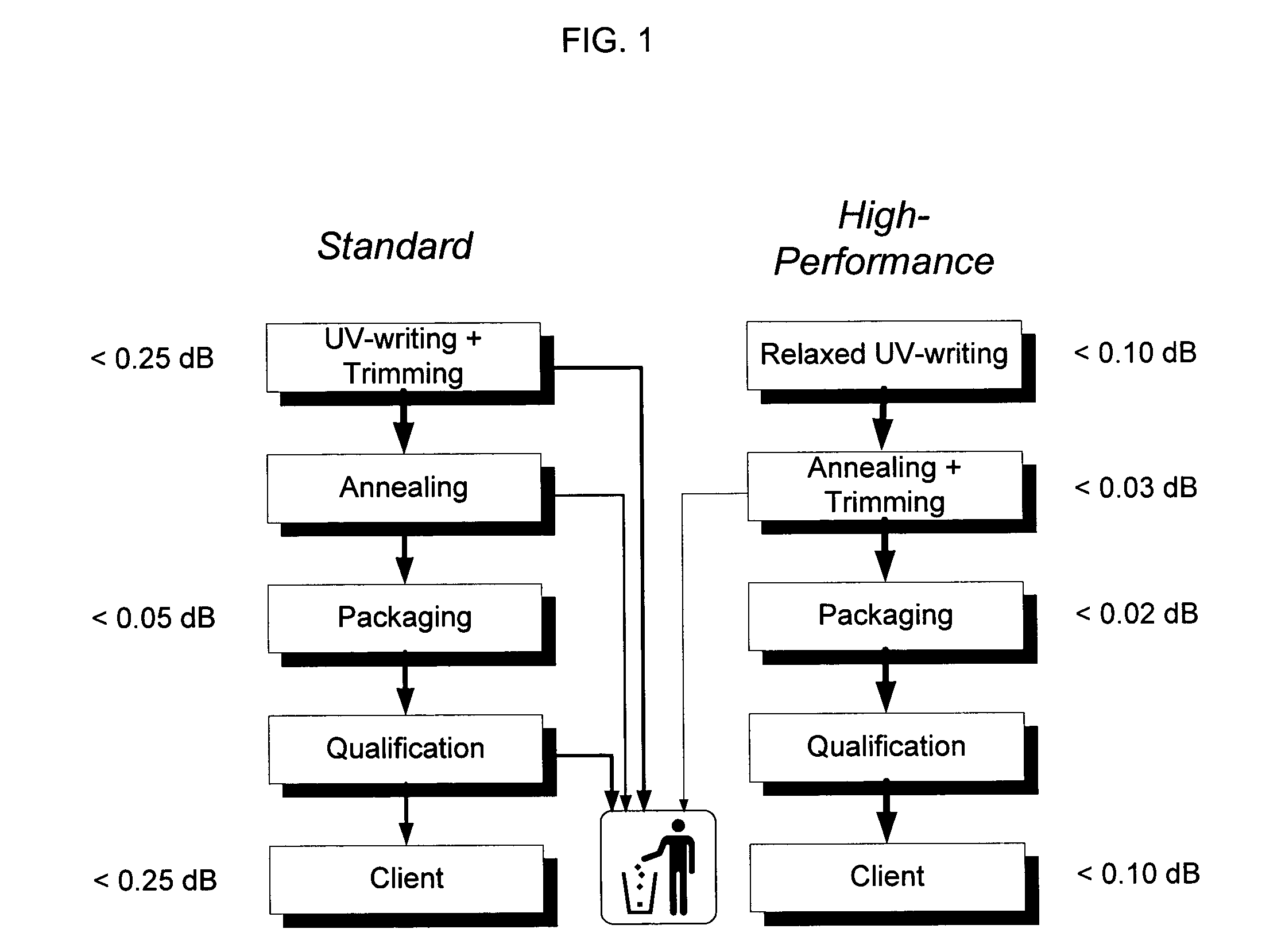
[0007] In accordance with an aspect of the present invention, the trimming and annealing steps are combined into a single process in order to efficiently fabricate complex FBG filters with improved performance.
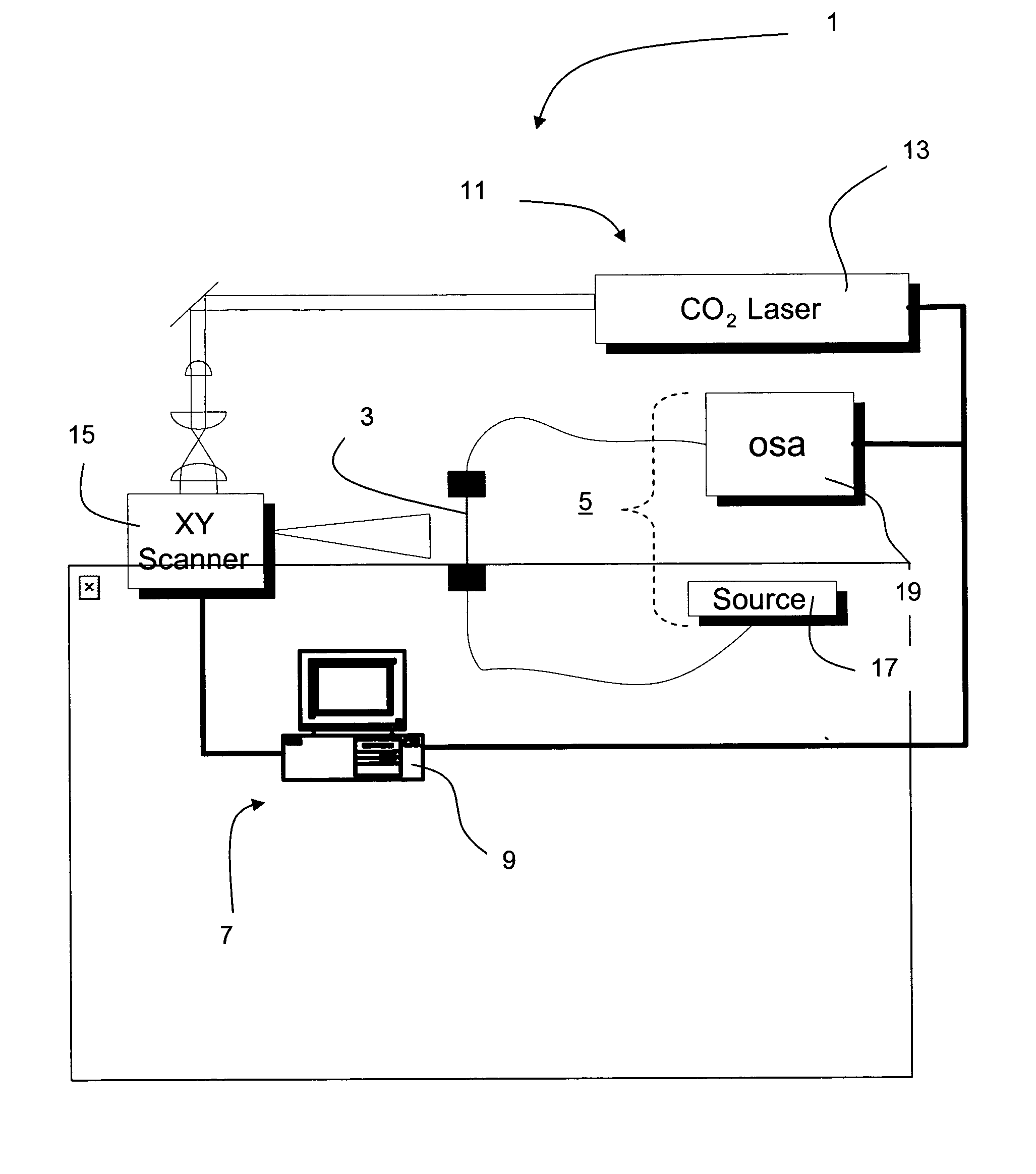
[0012] ii) generating a controlled complex temperature profile along the FBG with a heating means according to the characteristic data for providing an accurate controlled annealing process of the FBG, thereby providing an accurate trimming thereof.
[0014] In another preferred embodiment of this method, the FBG is a gain flattening filter having a spectral response matching an inverse gain profile of an amplifier within the gain flattening filter is incorporated for flattening a gain of the amplifier. Preferably, the gain flattening filter has an improved insertion loss error function which is advantageously smaller than + / -0.15 dB.
[0015] According to another aspect of the present invention, there is provided an annealing-trimming apparatus for manufacturing a FBG having improved performances. The annealing-trimming apparatus is provided with an analysing means operatively connected to a UV-written FBG provided in an optical fiber for monitoring characteristic data of the FBG. The annealing-trimming apparatus is also provided with a processing means operatively connected to the analysing means for processing the characteristic data. The annealing-trimming apparatus is also provided with a heating means operatively connected to the processing means for generating a controlled complex temperature profile along the FBG according to the characteristic data, thereby providing an accurate annealing-trimming of the FBG.
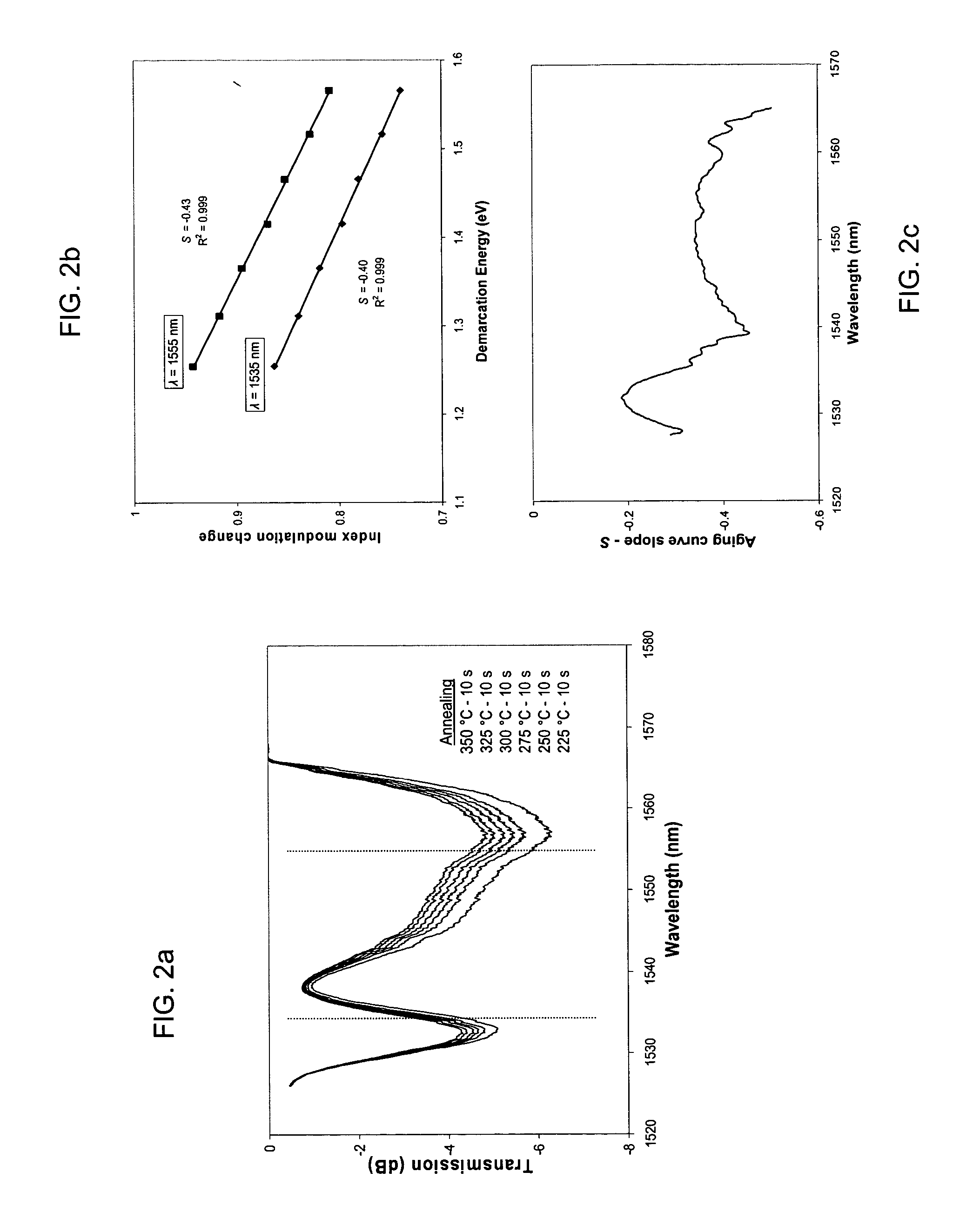
[0017] Advantageously, the present invention makes possible the creation of any desired temperature profile along the length of the FBG. It allows to precisely locate the FBG in space, and to affect local correction to the FBG spectral curve without affecting nearby points. The method and apparatus of the present invention also make it possible to estimate the necessary time and temperature to affect the required correction and end-of-life performance of the FBG after final processing, and estimate and take into account cladding mode losses of the FBG. Systematic errors between the final spectral curve and the target curve on a cascaded series of FBGs are advantageously reduced.

Problems solved by technology

In the case of thin film filters-gain flattening filter, the manufacturing process is such that all gain flattening filters have very similar error functions of the order of .+-.0.25 dB and these systematic errors can add up to unacceptable levels.
However, imperfections in the phase mask, mechanical and laser instabilities make it very difficult to obtain ILEF smaller than .+-.0.15 dB.
In those cases, a lengthy manual UV-trimming process is often required.
Even then, the subsequent temperature annealing process can slightly distort the final spectral shape and the resulting production yield is low.
Finally, because the UV-trimming process is operator dependent, it often leads to small but noticeable systematic errors in the ILEF.

Method used


Image

  • Method for manufacturing a FBG having improved performances and an annealing-trimming apparatus for making the same
  • Method for manufacturing a FBG having improved performances and an annealing-trimming apparatus for making the same
  • Method for manufacturing a FBG having improved performances and an annealing-trimming apparatus for making the same

Examples


Embodiment Construction

[0030] In the following description, similar features in the drawings have been given similar reference numerals and in order to weight down the figures, some elements are not referred to in some figures if they were already identified in a preceding figure.

[0031] This invention relates in particular to a method and apparatus to quickly modify the spectral response curve of FBG filters in order to precisely match a pre-defined target spectra, most often but not exclusively the inverse gain profile of an Er doped fiber amplifier (EDFA). The invention provides a method and apparatus to create any desired temperature profile along the length of the FBG; a mean to precisely locate the FBG in space; a mean to affect local correction to the FBG spectral curve without affecting nearby points; a mean to estimate the necessary time and temperature to affect the required correction; a mean to estimate end-of-life performance of the FBG after final processing; a mean to reduce systematic error...


PUM


Abstract

A method for manufacturing a FBG having improved performances and an annealing-trimming apparatus for making the same are provided. The trimming and the annealing steps are advantageously combined into a single process in order to efficiently fabricate complex FBG filters with improved performance. The method comprises the steps of UV-writing a FBG in an optical fiber prior to annealing-trimming characteristics of the FBG by performing the sub-steps of monitoring characteristic data of the FBG while generating a controlled complex temperature profile along the FBG with a heating means according to the characteristic data for providing an accurate controlled annealing process of the FBG, thereby providing an accurate trimming thereof.

Description

[0001] The present invention generally relates to a method and an apparatus for manufacturing fiber Bragg gratings (FBGs) having improved performances. More particularly, the invention concerns a method and apparatus wherein the trimming of the FBG and the annealing thereof steps are combined in order to efficiently manufacture FBGs with improved performance.[0002] FBGs and chirped FBGs are widely used technologies to fabricate complex filters. Gain flattening filters for erbium doped fiber amplifiers (EDFAs) are but one example. Gain flatness of optical amplifiers over the communication bandwidth is a key requirement of high performance optical Wavelength Division Multiplexing (WDM) communication systems. Usually, a gain flattening filter with a spectral response matching the inverse gain profile is incorporated within the amplifier to flatten its gain.[0003] Several gain flattening filter technologies can be used to perform the gain equalization, thin film filters and chirped FBGs...

Claims


Application Information

Patent Timeline
Patent Type & Authority Applications(United States)
IPC IPC(8): G02B5/18G02B6/02
CPCG02B6/02185G02B5/1857
Inventor BERNARD, PIERREGREGOIRE, NATHALIELAFRANCE, GHISLAIN
Owner TERAXION
Learn More