
Method and device for controlling a computer program by means of an intraoral scanner

a computer program and scanner technology, applied in the field of computer program and intraoral scanner, can solve the problems of no known method for non-contact control of cad/cam software, and voice control is not available in such systems

Active Publication Date: 2016-01-07
DENTSPLY SIRONA INC
View PDF1 Cites 10 Cited by
  • Summary
  • Abstract
  • Description
  • Claims
  • Application Information

AI Technical Summary

Benefits of technology

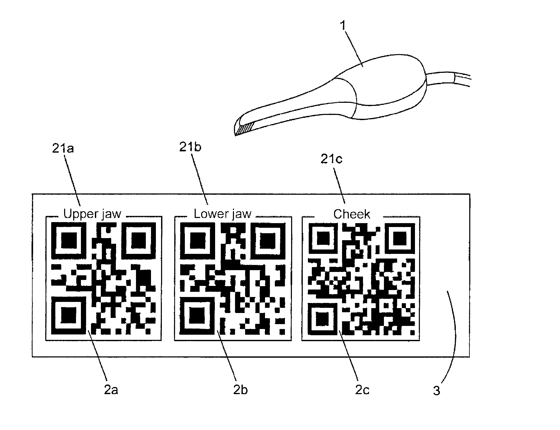
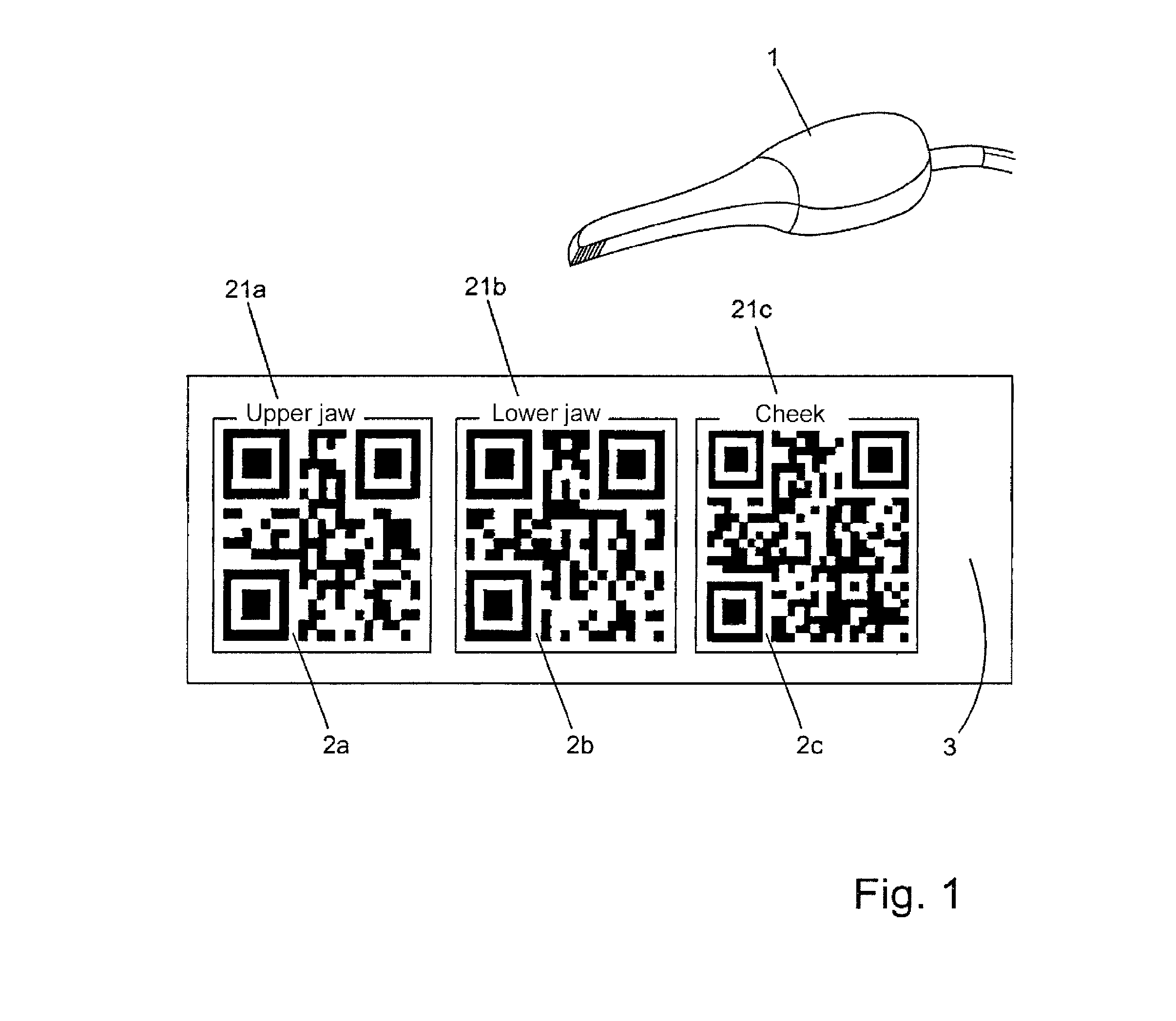
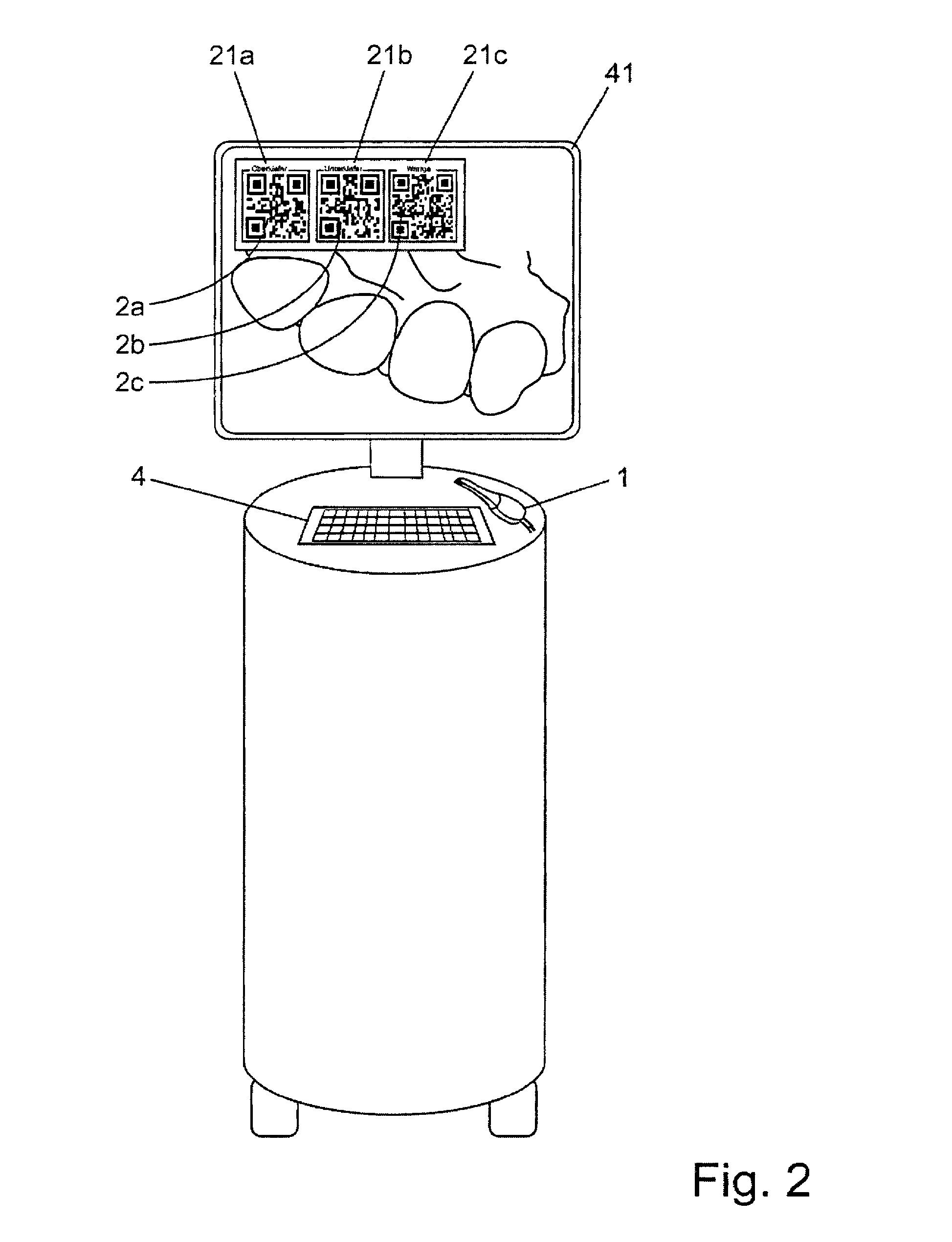
The invention is a method for controlling a computer program for dental procedures using an intraoral scanner. The method involves detecting optical markers on an optical marker and switching the program to a predetermined state based on the marker. The program can control functions such as image field changes, image region deletion, image calculation, and patient data record input. The optical markers can be applied to the scanner or to a scan body, and the program can switch to different resolutions or start a proposal calculation. The invention also includes a computer program that displays optical markers on a monitor for controlling the program. The optical markers can be generated based on software or printed onto a label. The invention allows for the use of the intraoral scanner for controlling the computer program, improving dental procedures.

Problems solved by technology

There are no known methods for non-contact control of CAD / CAM software that do not require control via an input interface on the respective computer system.
Voice control is not available for such systems because it is susceptible to problems due to the mouth protection worn by the dentist and ambient noise that cannot be avoided in a dentist's office, and it would have to be learned first, if necessary.

Method used


Image

  • Method and device for controlling a computer program by means of an intraoral scanner
  • Method and device for controlling a computer program by means of an intraoral scanner
  • Method and device for controlling a computer program by means of an intraoral scanner

Examples


Embodiment Construction

[0005]This object is achieved by the method according to the invention for controlling a computer program, wherein when an optical marker is detected by an intraoral scanner, and a control signal is sent to the computer program and switches the computer program to a predetermined state. The scanner is in particular a 2D camera or a 3D scanner. The computer program is a CAD / CAM program.

[0006]The predetermined state is selected from the group consisting of a change in an image field, deletion of an image region, an image calculation, a restoration calculation and input of a patient's name. It is possible in this way for the dentist to control the functions of the CAD / CAM program without taking the intraoral scanner out of his hand. Thus, for example, when recording an image, he can change the image field by aiming the intraoral scanner at a marker assigned to this state. It is also possible for him in this way to change the image field by aiming the intraoral scanner at a marker assig...


PUM


Abstract

The present invention relates to a computer program and to a method for controlling the computer program, wherein a control signal is sent to the computer program when an optical marker, in particular a two-dimensional barcode (2a, 2b, 2c), is detected by an intraoral scanner (1), which signal switches the computer program to a predefined state. A device for controlling the computer program comprises a support (3) on which at least one optical marker is arranged. The optical marker has an inscription (21a, 21b, 21c) which indicates a state of the computer program to which the computer program can be switched by detection of the optical marker by the intraoral scanner (1).

Description

TECHNICAL FIELD[0001]The present invention relates to a computer program as well as a method and a device for controlling the computer program by means of an intraoral scanner. In addition, the invention relates to a data medium that stores the computer program according to the invention. Furthermore, the invention relates to the use of an intraoral scanner for controlling a computer program and a device that comprises an intraoral scanner and is designed to generate a control signal when an optical marker is detected by the intraoral scanner.PRIOR ART[0002]Intraoral scanning systems enable a dentist to create three-dimensional representations of the oral cavity by means of a continuous recording method or by recording a few individual images. The head of a handheld camera is therefore guided at a small distance over the teeth to be recorded. A three-dimensional model can be created from the data compiled by means of the camera by using CAD / CAM software (computer aided design / comput...

Claims


Application Information

Patent Timeline
IPC IPC(8): A61C5/77A61C13/00A61B1/00A61B1/24G06F19/00
CPCA61C13/0004G06F19/3437A61B1/00039A61B1/24A61C2204/005A61C9/0053A61B90/94G16H50/50A61B1/00006A61B1/0004
Inventor SCHNEIDER, SASCHA
Owner DENTSPLY SIRONA INC
Learn More