Controller for machine tool

Active Publication Date: 2016-01-07
FANUC CORP
View PDF4 Cites 14 Cited by
  • Summary
  • Abstract
  • Description
  • Claims
  • Application Information

AI Technical Summary

Benefits of technology

[0018]According to the present invention configured as described above, the feed screw and the spindle are driven so as to agree with the thermal displacement state at the time of saturation of the thermal displacement, whereby warm-up operation can be achieved without entailing wasteful operation and the warm-up time can be reduced. The spindle is intermittently accelerated and decelerated at a rotational speed not lower than that for actual workpiece machining, whi

Problems solved by technology

This change of the machine position due to the heating causes a problem in high-precision machining.
However, the time and details of the idling are determined based on the experience and intuition of a skilled operator, so that wasteful warm-up time may possibly occur.
Therefore, the warm-up operation involves many wasteful operations, such as a dwelling operation commanded during machining, low-speed machining operation, and tool change operation, and entails extra time for that.
Although the timing for ending the warm-up operation can be determined according to the technique described above, the reduction of the warm-up time is limited, since the efficiency of the warm-up operation is invariable.
Further, the object to be the warmed up is limited t

Method used


Image

  • Controller for machine tool
  • Controller for machine tool
  • Controller for machine tool

Examples


Embodiment Construction

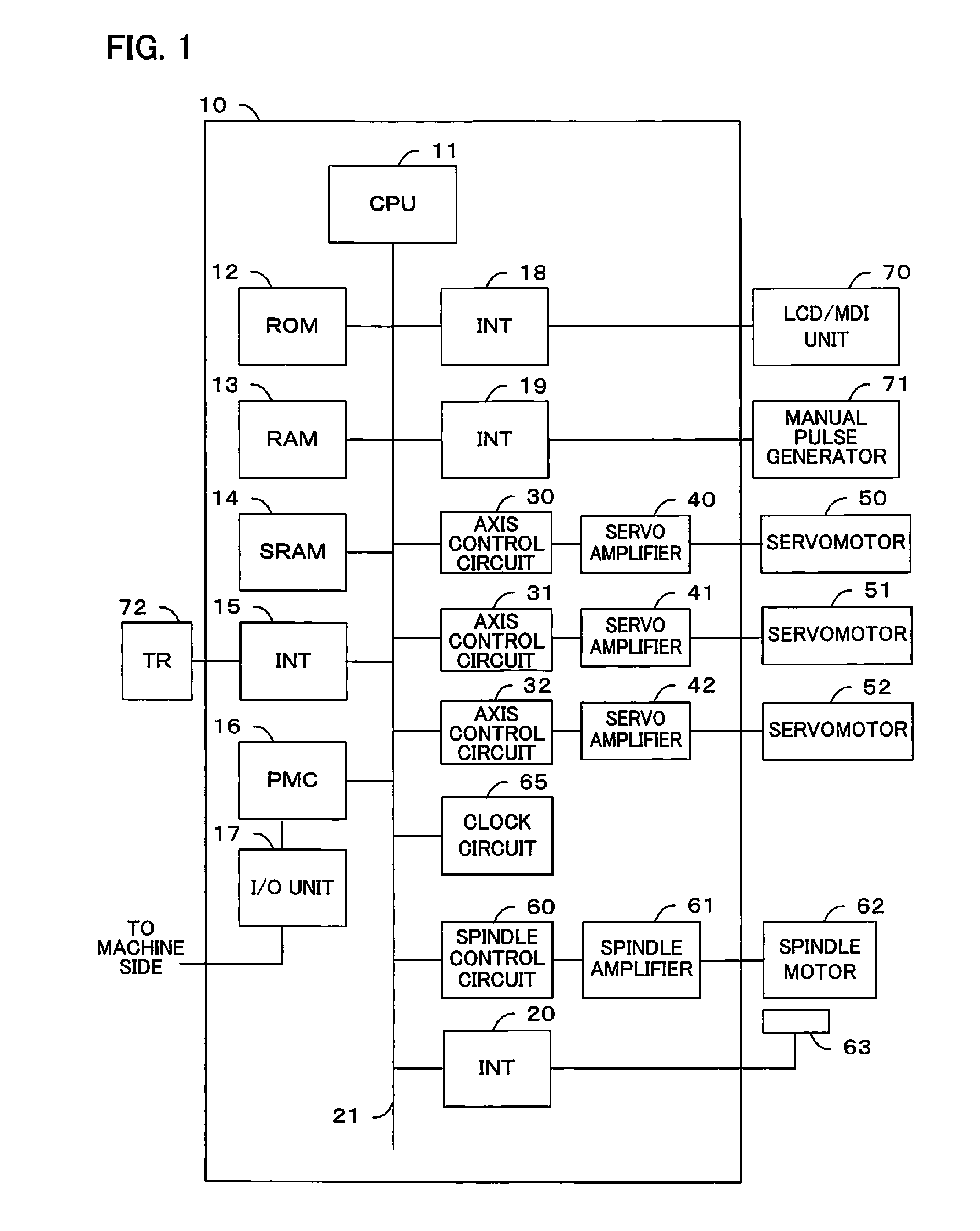
[0032]A controller for a machine tool according to the present invention will be described with reference to the block diagram of FIG. 1 showing a numerical controller.

[0033]A numerical controller 10 for controlling a machine tool constitutes a thermal displacement compensation device (described later) for the machine tool. A processor (CPU) 11 of the numerical controller 10 reads a system program stored in a ROM 12 through a bus 21 and generally controls the numerical controller 10 according to the read system program. A RAM 13 is loaded with temporary calculation data, display data, various data input by an operator through an LCD / MDI unit (manual data input device with a liquid crystal display) 70, and the like.

[0034]An SRAM 14 is constructed as a nonvolatile memory, which is backed up by a battery (not shown) so that it can maintain its storage state even after the numerical controller 10 is powered off. The SRAM 14 is stored with a program for the measurement of an initial posi...


PUM


Abstract

A thermal displacement state (target thermal displacement state) in which thermal displacement of a machine tool is saturated when the machine tool is operated based on a machining program is previously stored, and a warm-up operation pattern of a motor is determined so as to approach the target thermal displacement state. The motor is driven based on the warm-up operation pattern and the warm-up operation of the motor is stopped if the thermal displacement state of the machine tool is within a predetermined range.

Description

BACKGROUND OF THE INVENTION[0001]1. Field of the Invention[0002]The present invention relates to a controller for a machine tool, and more particularly, to a controller for a machine tool configured to perform efficient warm-up control based on a thermal displacement state at the point in time when thermal displacement is saturated.[0003]2. Description of the Related Art[0004]In a machine tool, a feed screw and a spindle are driven by a motor, so that they are expanded to inevitably change the machine position by heating of the motor, frictional heat due to rotation of a bearing, and frictional heat from a contact portion between a ball screw and a ball nut. Thus, the relative positions of a tool and a workpiece to be machined are shifted. This change of the machine position due to the heating causes a problem in high-precision machining.[0005]The displacement of the machine position by heat can be removed by using the following methods. One of these methods is a technique in which ...

Claims


Application Information

Patent Timeline
IPC IPC(8): B23Q11/14B23Q11/00B23Q15/12B23Q15/18G05B19/404
CPCB23Q11/14B23Q11/0007B23Q15/12G05B2219/37429G05B19/404G05B2219/37428B23Q15/18B23Q15/00G05B2219/49204G05B2219/49213
Inventor KOYAMA, YASUAKI
Owner FANUC CORP
Why Eureka
Try Eureka