Air compression device

a technology of air compression and filter, which is applied in the direction of machines/engines, liquid fuel engines, separation processes, etc., can solve the problems of large increase in maintenance costs and large amount of dust accumulated in filters, and achieve the effect of reducing maintenance costs and excessive degradation of dust removal performan

Inactive Publication Date: 2016-01-07
NABLESCO CORP
View PDF92 Cites 3 Cited by
  • Summary
  • Abstract
  • Description
  • Claims
  • Application Information

AI Technical Summary

Benefits of technology

[0011]The aforementioned air compression device may contribute to a reduction in maintenance cost for dust removal without excessive degradation in dust removal performance.

Problems solved by technology

When a train runs in a region in which a lot of dust floats, a filter catches a large amount of dust in a short period of time.
The frequent filter exchange results in a large increase in maintenance cost.

Method used


Image

  • Air compression device
  • Air compression device
  • Air compression device

Examples


Embodiment Construction

[0026]An exemplary air compression device is described below with reference to the drawings. The principle of the air compression device to be clarified by the following description is widely applicable to a variety of air compression devices which are attached to train coaches or other vehicles.

[Installation of Air Compression Device]

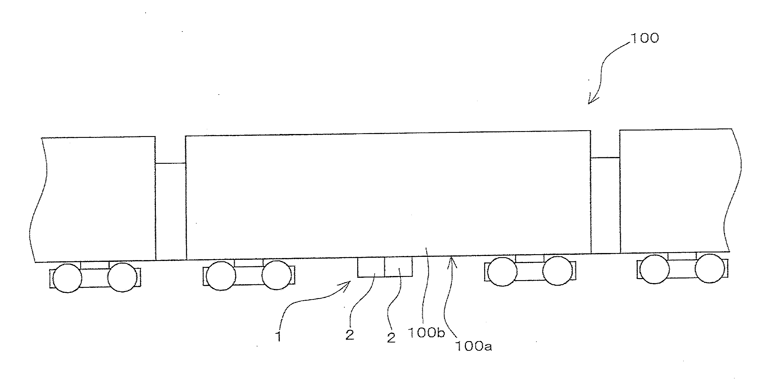
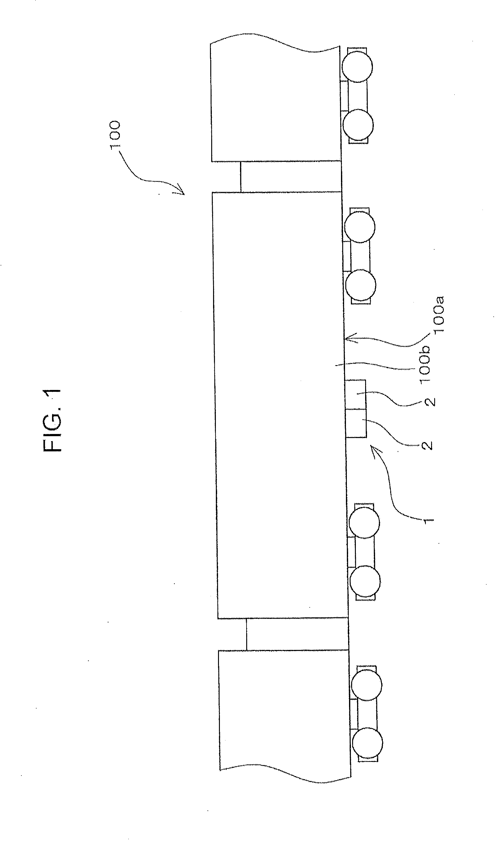
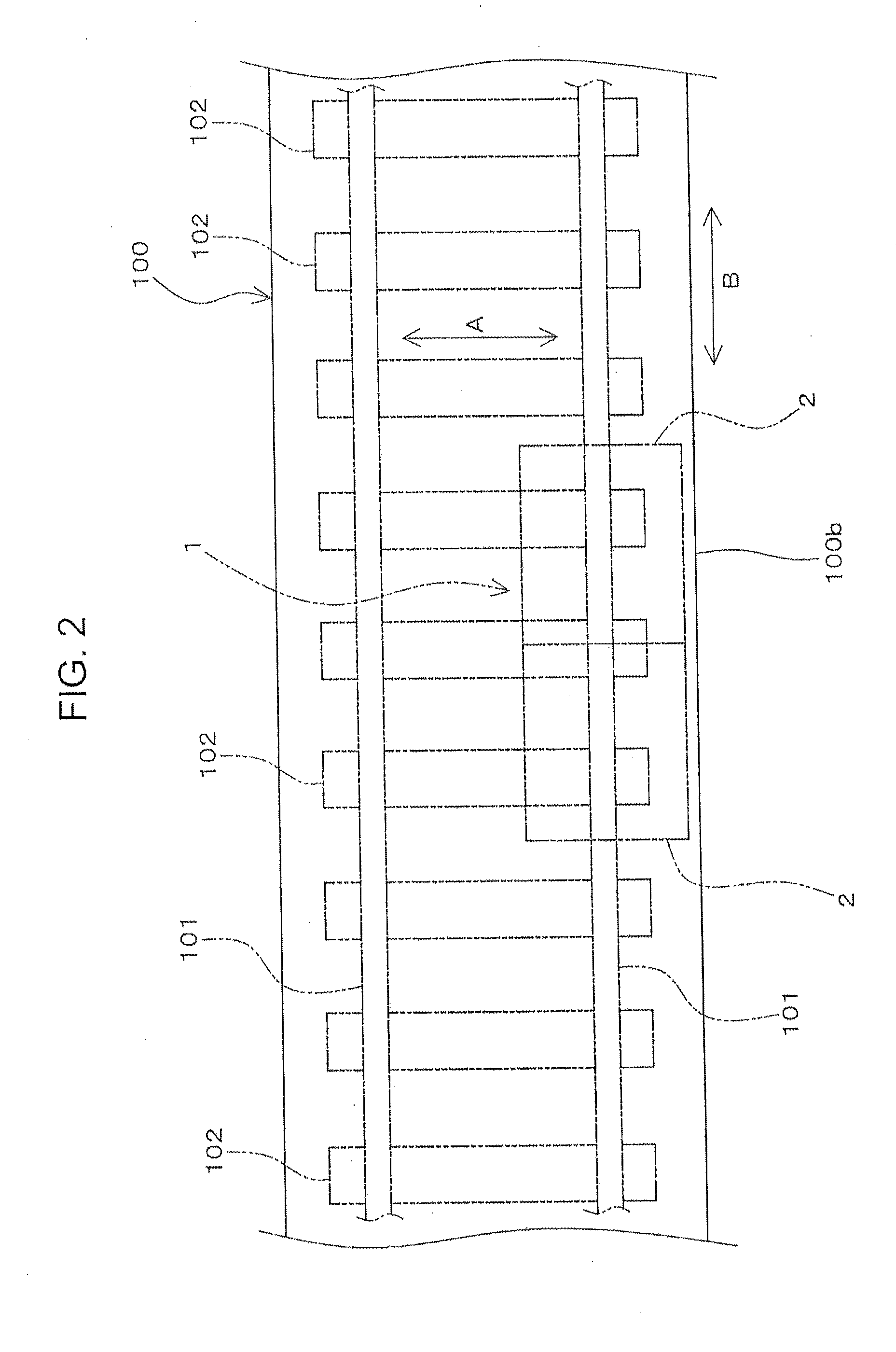
[0027]FIG. 1 is a schematic view of an air compression device 1 attached to a vehicle 100. In the present embodiment, the vehicle 100 is a train coach. Alternatively, the air compression device 1 may be attached to another vehicle (e.g. an automobile). FIG. 2 is a schematic plan view showing an attachment position of the air compression device 1 in the vehicle 100.

[0028]As shown in FIGS. 1 and 2, the air compression device 1 includes two air compressor units 2. The air compression device 1 may include one air compressor unit Alternatively, the air compression device 1 may include three or more air compressor units 2. The principle of the embodiment is ...


PUM

PropertyMeasurementUnit
intersection angleaaaaaaaaaa
thicknessaaaaaaaaaa
intersection angle θ1aaaaaaaaaa

Abstract

The present application discloses an air compression device, including a housing in which an air compressor is stored, the air compressor being configured to generate compressed air; and a filter through which air passes, the air being sucked into the housing. The filter may include a plate member having a first main plate portion provided with air holes through which the air passes. A surface of the first main plate portion is oriented in a first direction, the air holes extending through the plate member in a second direction intersecting with the first direction so as to change a flow direction of the air.

Description

BACKGROUND OF THE INVENTION[0001]1. Field of the Invention[0002]The present invention relates to an air compression device which is attached to a vehicle.[0003]2. Description of the Related Art[0004]An air compression device is attached to a vehicle (e.g. a train coach). The air compression device generates compressed air to be used in the vehicle (c.f. Japanese Utility Model Registration No. 3150077, hereinafter, simply called as Patent Document 1).[0005]Patent Document 1 discloses an air compression device including filters, air compressors and driving motors. Each of the filters blocks passage of foreign matters (e.g. dust in the air). The air passing through each of the filters is fed to each of the air compressors. Each of the air compressors is driven by each of the driving motors for compressing the air.[0006]Patent Document 2 (JP 2010-55973 A) discloses a housing, in which a battery module is stored. The housing is situated beneath a floor of a train coach. A filter unit is ...

Claims


Application Information

Patent Timeline
Patent Type & Authority Applications(United States)
IPC IPC(8): F04C18/02B61D27/00F04C29/00F04C29/04F04D19/00F04D25/16
CPCB61D27/0018F04C18/0215F04D25/166F04C29/04F04D19/002F04C29/0085B01D45/04B01D45/06B01D45/08F04B53/20F04D29/70
Inventor MIZUFUNE, TORUKUROMITSU, MASARUTAKAHASHI, AKIRA
Owner NABLESCO CORP
Why Eureka
Try Eureka