Chemical vapour deposition device

Active Publication Date: 2016-01-07
KOBUS SAS
View PDF0 Cites 31 Cited by
  • Summary
  • Abstract
  • Description
  • Claims
  • Application Information

AI Technical Summary

Benefits of technology

[0013]The invention provides a

Problems solved by technology

Accidental reactions between the gases or between a gas and a wall can occur and lead to solid deposits in the form of accidental films in unwanted places.
Accidental reactions can cause clogging of apertures of a gas discharge assembly and particularly the gas discharge ring.
The clogging of some apertures disturbs the circulation of the gases and the quality of the products is affected thereby.
Moreover, the gas discharge assembly, once blocked, no longer fulfils its function adequately.
The rest of the equipment, and particularly the reaction chamber, is in turn subject to accidental reactions at its surface.
The particular

Method used


Image

  • Chemical vapour deposition device
  • Chemical vapour deposition device
  • Chemical vapour deposition device

Examples


Example

[0036]The appended drawings comprise elements of certain nature. They can therefore not only be used to complete the invention, but also to contribute to its definition where applicable.

DETAILED DESCRIPTION

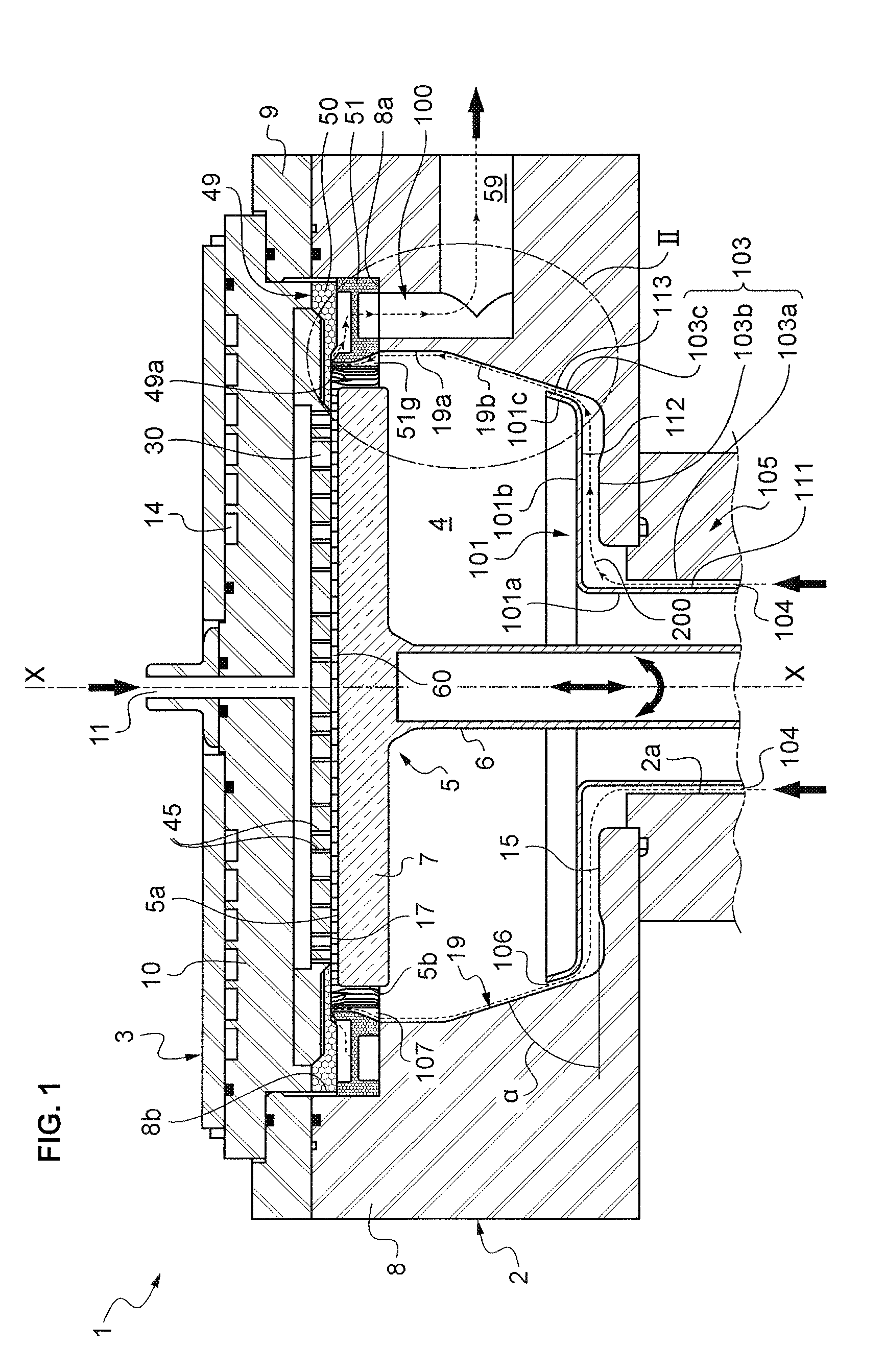
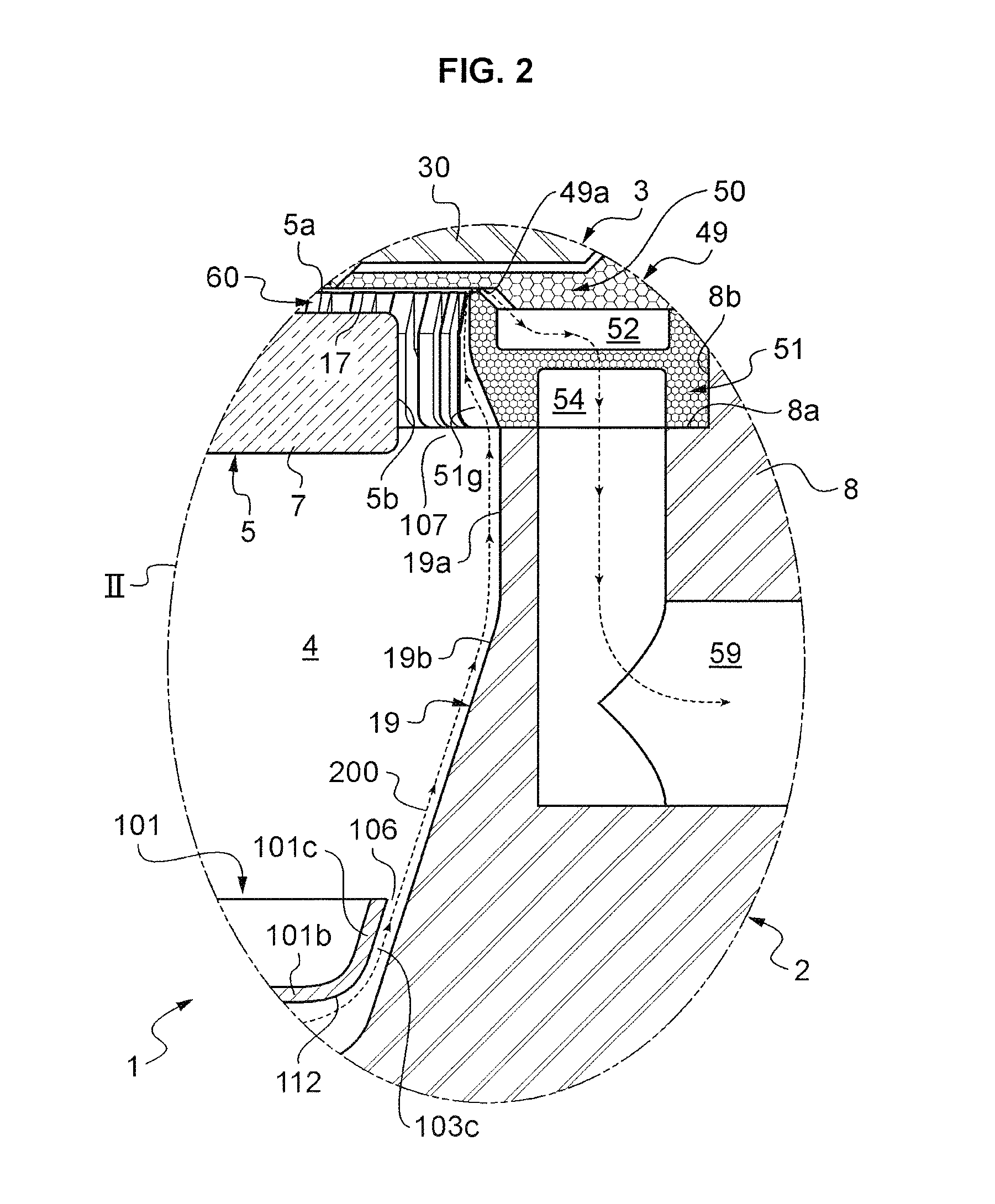
[0037]The figures show a processing device, or reactor with the overall reference number 1. In general, the processing device 1 has rotational symmetry about a central axis XX. This promotes the homogeneity of the chemical reactions and facilitates fabrication. This symmetry can have a few exceptions. On the drawings, this axis is vertical, which corresponds to the usual disposition of the device in operation. In the remainder of the text, the terms top, bottom, horizontal and vertical are used in accordance with the representation in FIGS. 1, 2 and 5. The reactor 1 has controlled pressure and temperature. The reactor 1 comprises a hollow body 2 and a lid 3 closing the body 2 to form a reaction chamber 4. The reaction chamber 4 can also be called an enclosure. The chamber 4 houses...


PUM

PropertyMeasurementUnit
Lengthaaaaaaaaaa
Thicknessaaaaaaaaaa
Heataaaaaaaaaa

Abstract

A reactor device for chemical vapor deposition comprises a reaction chamber having a purge gas inlet. A gas discharge channel is linked to said reaction chamber via a circumferential opening in the inner wall of said chamber. The reaction chamber is arranged such that a purge gas stream flows from the purge gas inlet to the discharge channel. Said inner wall of the reaction chamber comprises means for exchanging heat with the purge gas, for example fins.

Description

CROSS-REFERENCE TO RELATED APPLICATIONS[0001]This application is a national phase entry under 35 U.S.C. §371 of International Patent Application PCT / EP2014 / 053457, filed Feb. 21, 2014, designating the United States of America and published as International Patent Publication WO 2014 / 128267 A2 on Aug. 28, 2014, which claims the benefit under Article 8 of the Patent Cooperation Treaty and under 35 U.S.C. §119(e) to French Patent Application Serial No. 1351526, filed Feb. 21, 2013, the disclosure of each of which is hereby incorporated herein in its entirety by this reference.TECHNICAL FIELD[0002]The invention falls within the domain of fabrication of integrated circuits or microsystems, and more particularly equipment and processes for vapor phase chemical deposition. The latter are also known in the prior art as “CVD” or “Chemical Vapor Deposition” methods equipment and processes.BACKGROUND[0003]Integrated circuits and microsystems are fabricated from wafers, or substrates, of silico...

Claims


Application Information

Patent Timeline
IPC IPC(8): C23C16/455C23C16/44
CPCC23C16/45572C23C16/4401C23C16/4408C23C16/4558C23C16/45504C23C16/45517C23C16/45521
Inventor NAL, PATRICEBOREAN, CHRISTOPHEVITIELLO, JULIEN
Owner KOBUS SAS
Why Eureka
Try Eureka