Personnel proximity detection and tracking system

Active Publication Date: 2016-01-07
VALVE SOULTIONS INC
View PDF2 Cites 48 Cited by
  • Summary
  • Abstract
  • Description
  • Claims
  • Application Information

AI Technical Summary

Benefits of technology

[0015]According to still a further feature of the present disclosure, there also can be provided a transmission power modifier associated with each of the transmitter elements, each of the transmission power modifiers modifying the effect of the actuating power supply upon the corresponding one of the transmitter elements such that a combined intensity of the electromagnetic signal from all of the transmitter elements reaching the part of the virtual line can be substantially constant along the line.
[0016]In another embodiment, the present disclosure can provide an infrared identification tracking method and system for hospitals and / or food processing hygiene compliance. In this embodiment, each healthcare person wears a badge on their chest. The badge can comprise, for example, at least three infrared LED's, for example, arranged in a configuration with one LED in the front and one LED on each side, and will provide a coded person's identification and position within a predetermined zone. Other configurations also can be used. The predetermined zone can be designated by several factors, such as, distance, front, right, left side seen from the orientation of the badge. The badge can also include at least one infrared receiver that functions to “wake up” the badge when the badge receives a signal from a dispenser or other tracking unit, such as those that are installed within a facility. Generally, the badge is in a ready state and can be woken up in order to provide for battery saving.

Problems solved by technology

Such bacteria have been linked to causing numerous infection outbreaks in health care facilities over the last decade, and can survive on surfaces for long periods of time.
These findings raise concerns since these contaminated surfaces are touched routinely by medical personnel and may be a source of hospital-based transmission of highly infectious diseases, such as staph, MRSA and other serious infections to patients.

Method used


Image

  • Personnel proximity detection and tracking system
  • Personnel proximity detection and tracking system
  • Personnel proximity detection and tracking system

Examples


Embodiment Construction

[0042]The following detailed description is provided as an enabling teaching of embodiments of the invention. Those skilled in the relevant art will recognize that many changes can be made to the embodiments described, while still obtaining the beneficial results. It will also be apparent that some of the desired benefits of the embodiments described can be obtained by selecting some of the features of the embodiments without utilizing other features. Accordingly, those who work in the art will recognize that many modifications and adaptations to the embodiments described are possible and may even be desirable in certain circumstances. Thus, the following description is provided as illustrative of the principles of the invention and not in limitation thereof, since the scope of the invention is defined by the claims.

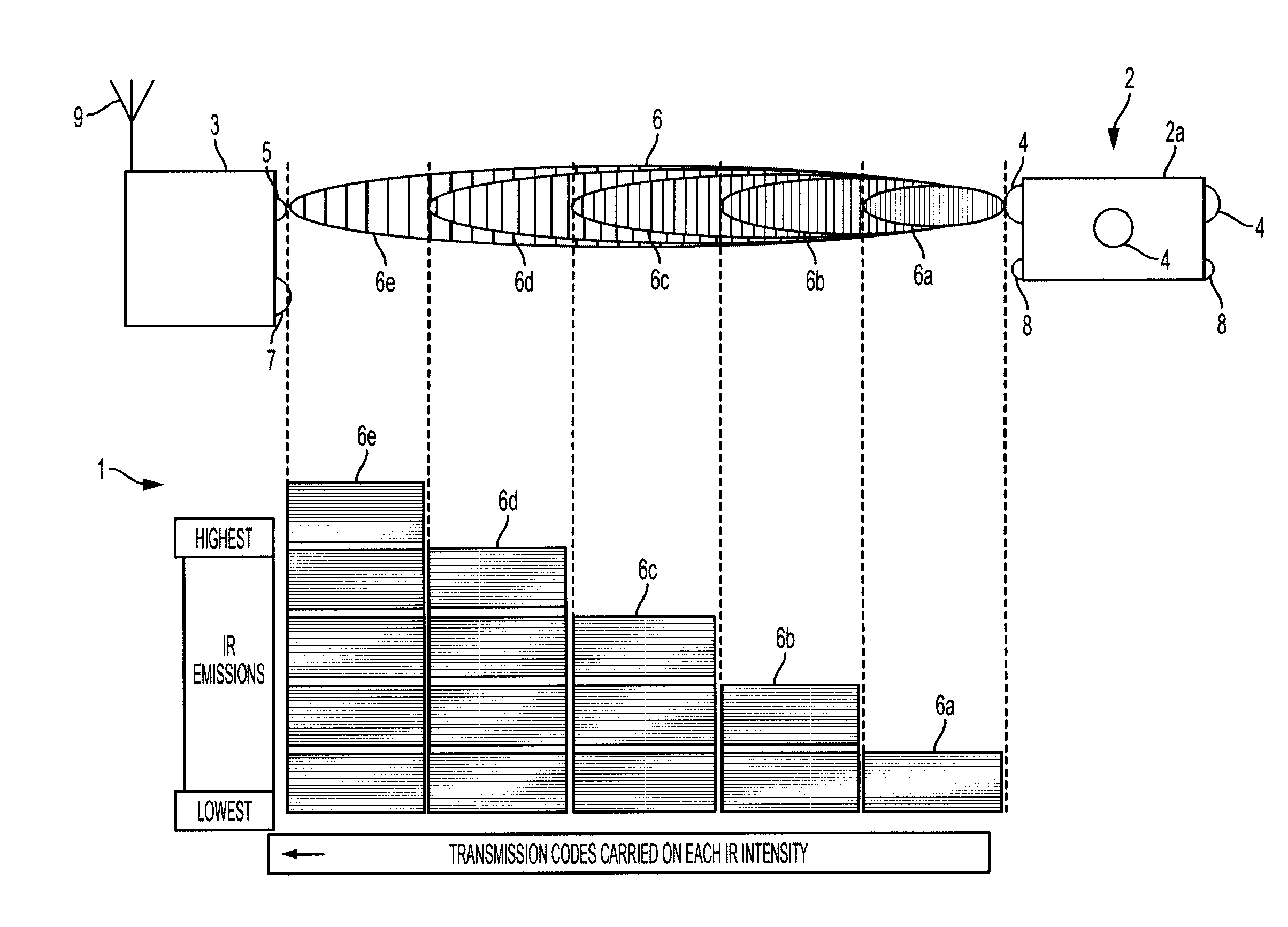
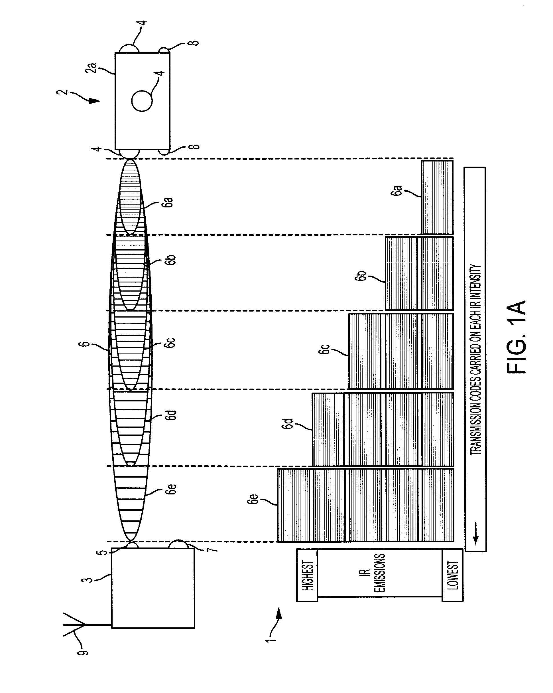
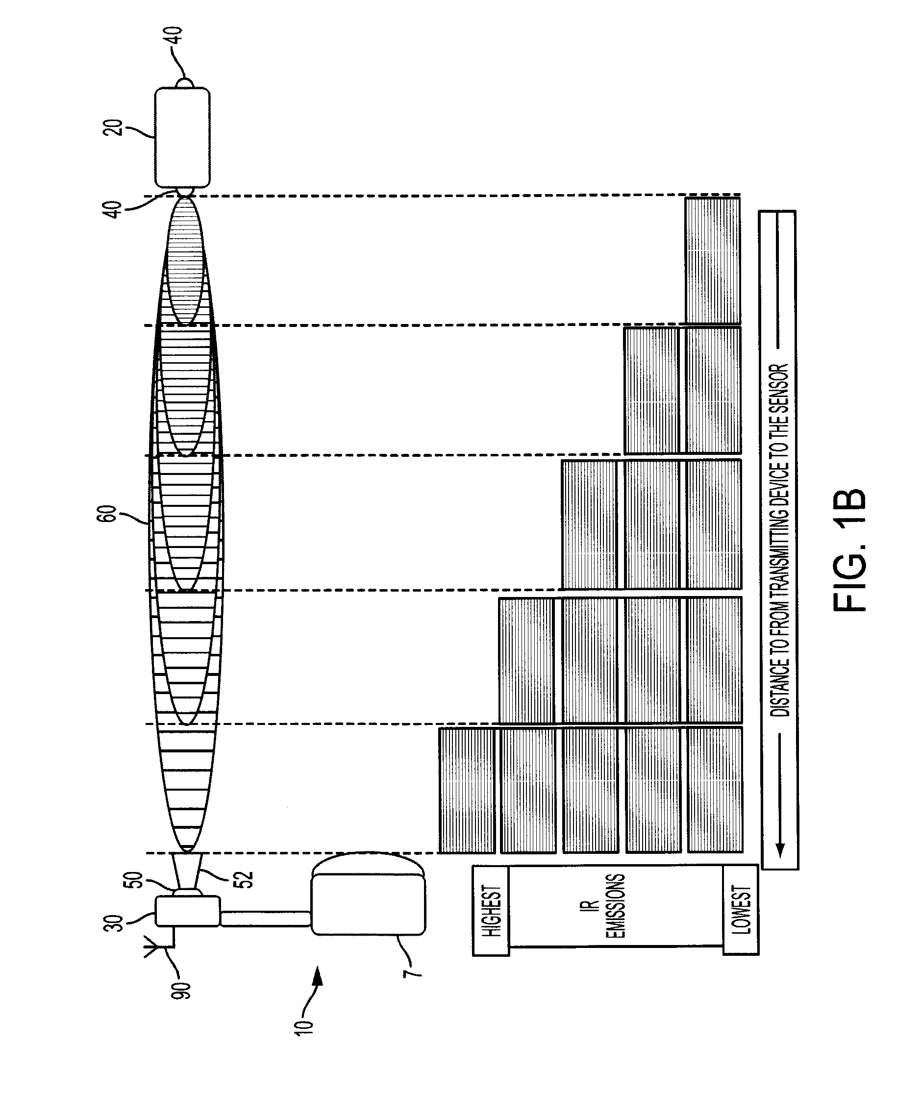
[0043]In general, embodiments of the present application can include multi-purpose methods and systems for tracking, identifying, locating, and / or mapping the movements ...


PUM


Abstract

Systems and methods for tracking, locating, identifying, or mapping movements of persons or personnel within a facility may include badges carried by selected persons or personnel through the facility, and these badges can each include a transmitter configured to transmit a series of signals including signature information identifying the badges and also identifying codes of each signal transmitted. In addition, a series of receivers can be positioned at selected locations of the facility and can receive the signals transmitted by the transmitters of the badges, and these receivers can be configured to identify each badge from which signals are received based upon signature information for identified badges and also to determine the proximity, range, distance, or zone between the badge identified and one or more receivers.

Description

CROSS REFERENCE TO RELATED APPLICATIONS[0001]The present patent application is a formalization of previously filed, co-pending U.S. Provisional Patent Application Ser. No. 62 / 020,728, filed Jul. 3, 2014 by the inventors named in the present application. This patent application claims the benefit of the filing date of this cited Provisional patent application according to the statutes and rules governing provisional patent applications, particularly 35 U.S.C. §119(e), and 37 C.F.R. §§1.78(a)(3) and 1.78(a)(4). The specification and drawings of the Provisional patent application referenced above are specifically incorporated herein by reference as if set forth in their entirety.TECHNICAL FIELD AND BACKGROUND[0002]In testing of areas of various facilities, such as hospital rooms, researchers have found antibiotic-resistant strains of bacteria on multiple surfaces, including bedrails, supply carts, and floors. Such bacteria have been linked to causing numerous infection outbreaks in hea...

Claims


Application Information

Patent Timeline
Patent Type & Authority Applications(United States)
IPC IPC(8): G08B21/24H04W4/02H04W4/029H04W4/33H04W4/38
CPCH04W4/02G08B21/245G16H40/20H04W4/38H04W4/33H04W4/029
Inventor LAUFER, ZOHAROSBORNE, JR., CHARLES AGNEW
Owner VALVE SOULTIONS INC
Why Eureka
Try Eureka