
Low battery indicator

a low battery and indicator technology, applied in secondary cell servicing/maintenance, instruments, heat measurement, etc., can solve the problems of increasing device complexity and cost, consuming more energy than an actuating, and consuming significant amounts of power, so as to save battery power and energy. , the effect of reducing the amount of energy

Inactive Publication Date: 2007-09-11
CONTECH ELECTRONICS
View PDF6 Cites 12 Cited by
  • Summary
  • Abstract
  • Description
  • Claims
  • Application Information

AI Technical Summary

Benefits of technology

[0010]The low battery indicating device according to the present invention requires very little energy from the battery to operate, and therefore the device can conserve the battery at a time when this is important.
[0011]The low battery indicating device according to the present invention uses energy from the battery during actuation for only a short period of time, and therefore the device does not need to continually drain the battery.

Problems solved by technology

This consumes more energy than an actuating mechanism which only requires a one time pulse of current through the muscle wire.
The disadvantage of these indicators is that they consume significant amounts of power, continuously from the batteries being checked, just at the time when power needs to be conserved.
It is possible to add a low power display such as an LCD panel, but adding one simply to display battery status would add significant complexity and cost to the device.

Method used


Image

  • Low battery indicator
  • Low battery indicator
  • Low battery indicator

Examples


Embodiment Construction

[0018]In the following description, similar features in the drawings have been given similar reference numerals.

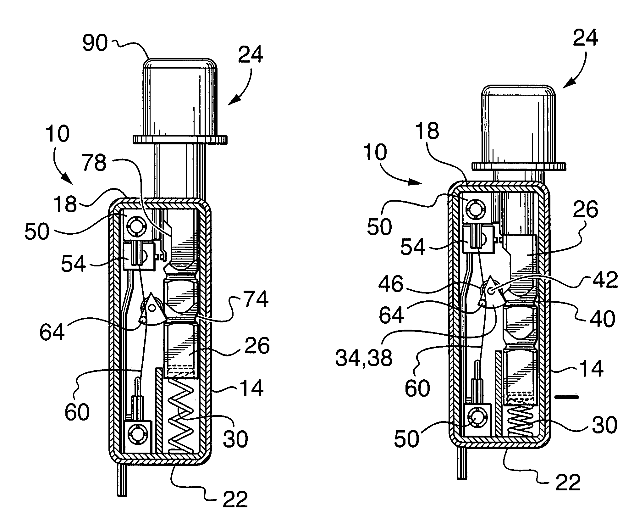
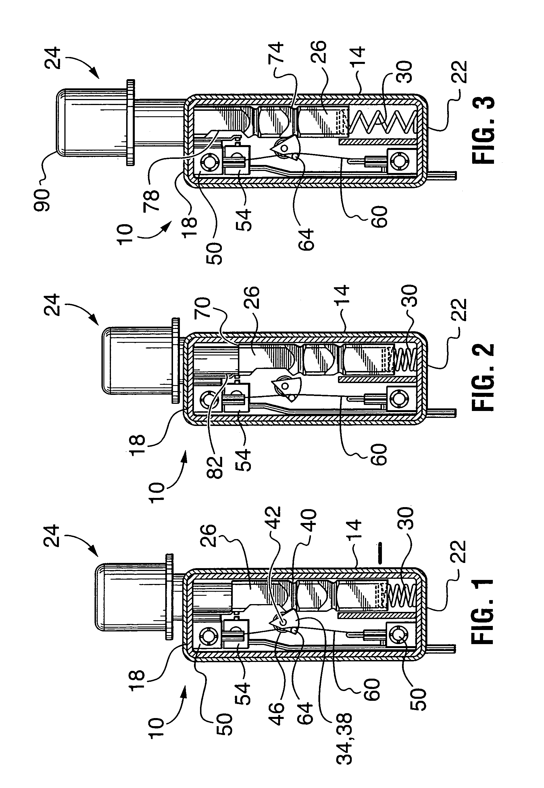
[0019]Turning to FIG. 1, there is illustrated an indicating device 10 for indicating that a battery (not illustrated) has low power. The device 10 is not intended to be used on its own, but rather it is integrated into a device (such as a consumer electronics device) including the battery. Most of the components of the device 10 are contained within a housing 14. The housing 14 includes a top wall 18 and a bottom wall 22. The housing 14 is preferably made of plastic or any other suitable conventional material.

[0020]Indicator 24, situated outside of housing 14, has an elongated body 26 which extends between the walls 18 and 22. A portion of the body 26 also extends through an aperture in the top wall 18. The indicator 24 is preferably made of plastic; however, it can also be made of other suitable materials.

[0021]When the indicator 24 is in a retracted position as illustrat...


PUM

PropertyMeasurementUnit
timeaaaaaaaaaa
poweraaaaaaaaaa
current flowaaaaaaaaaa

Abstract

A low battery indicating device is disclosed for indicating that a battery has low power. The device includes an indicator having a body movable between a retracted, unactuated position and an extended, actuated position. The indicator is visible when in the actuated position. The device also includes means for biasing the indicator towards the actuated position, and latch means cooperating with a portion of the body of the indicator, when the latch means is in a stop position, to hold the indicator in its unactuated position. The latch means is movable between the stop position and a go position which frees the indicator to move, under operation of the biasing means, to the actuated position. A memory alloy wire is mechanically associated with the latch means so as to leave the latch means in the stop position when the memory alloy wire is in a relaxed state and to move the latch means to the go position when the memory alloy wire is in a contracted state caused by heating of the memory alloy wire. Electrical sensor circuitry is in communication with the memory alloy wire. The electrical sensor circuitry is adapted to detect when the battery means has low power and cause heating of the memory alloy wire to cause it to change to the contracted state and thereby move the latch means to the go position.

Description

FIELD OF THE INVENTION[0001]The present invention relates to low battery indicators and, in particular, a low battery indicating device having minimal energy consumption.BACKGROUND OF THE INVENTION[0002]It is known to use shape memory alloy wire (SMA wire) in association with latch-based mechanisms. Memory alloy wire (or muscle wire) has a unique property in that it will contract (e.g. 4% in length) when it is heated. When used in a latch mechanism, the muscle wire is hooked onto or attached to the latch. When the muscle wire is in its expanded state, the latch can be engaged, and when the muscle wire is in a contracted state, the latch can be disengaged.[0003]U.S. Pat. No. 5,629,662 of Floyd et al. issued May 13, 1997 discloses a low energy memory metal actuated latch (low energy here being in reference to a small amount of energy which needs to be supplied to the memory alloy wire). The patent describes the use of a memory metal actuator including a length of memory wire, in a sys...

Claims


Application Information

Patent Timeline
Patent Type & Authority Patents(United States)
IPC IPC(8): H01H37/08G01K5/60G08B5/32H01H37/50H01M10/48
CPCH01M10/488H01M10/42Y02E60/10
Inventor BOLDA, GERRYJOHNSTON, PAULREYNOLDS, JORDON
Owner CONTECH ELECTRONICS
Learn More