

Communication terminal and radio communication method
A communication terminal and control channel technology, applied in wireless communication, selection device, multiplex communication, etc., can solve problems such as ineffective use of code resources
- Summary
- Abstract
- Description
- Claims
- Application Information
AI Technical Summary
Problems solved by technology
Method used
Image

Examples
Embodiment 1
[0023] In this embodiment, in a multi-carrier communication system using OFDM (Orthogonal Frequency Division Multiplex: Orthogonal Frequency Division Multiplexing) method, it will be described that an access channel serving as a control channel is allocated to subcarriers fewer than subcarriers of a traffic channel. , the case of accessing a grouped communication terminal device.
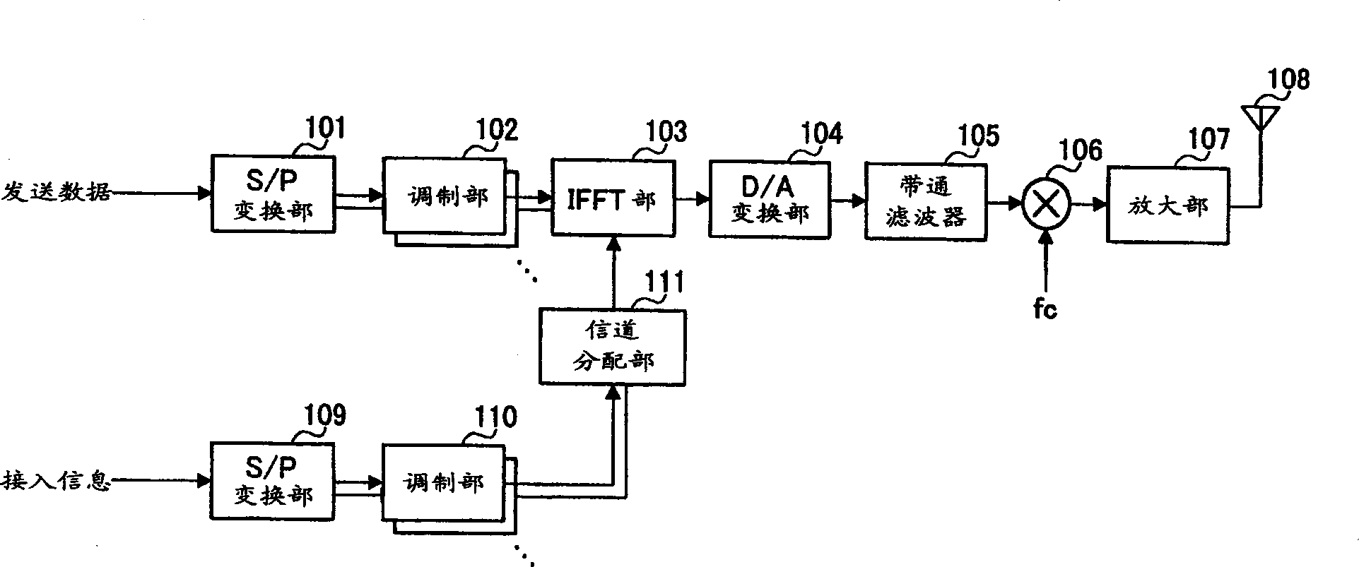
[0024] figure 1 A block diagram showing the configuration of a communication terminal device according to Embodiment 1 of the present invention. exist figure 1 In the communication terminal device shown, transmission data is converted into parallel signals in a serial / parallel (S / P) conversion unit 101 , and each parallel signal is output to a modulation unit 102 . Each modulation section 102 performs digital modulation processing on an input signal, and outputs the modulated signal to an IFFT (Inverse Fast Fourier Transform) section 103 .
[0025] On the other hand, the access information is con...
Embodiment 2
[0044] In this embodiment, in a multicarrier communication system using the OFDM scheme, a case will be described in which an access channel serving as a control channel is assigned to a designated subcarrier to access grouped communication terminal devices.
[0045] Figure 4 A block diagram showing the configuration of a communication terminal device according to Embodiment 2 of the present invention. exist Figure 4 In the communication terminal device shown, transmission data is converted into parallel signals in the S / P conversion unit 401 , and each parallel signal is output to the modulation unit 402 . Each modulation section 402 performs digital modulation processing on an input signal, and outputs the modulated signal to the IFFT section 403 .
[0046] The IFFT section 403 performs IFFT transformation on the digitally modulated transmission data, and outputs the IFFT-transformed signal to the D / A conversion section 404 . The D / A converter 404 converts the IFFT-tran...
Embodiment 3
[0065] In this embodiment, in a CDMA (Code Division Multiple Access: Code Division Multiple Access) multi-code communication system, the number of spreading codes assigned to the access channel serving as the control channel is less than that of the traffic channel. , the case of accessing a grouped communication terminal device.
[0066] Figure 7 A block diagram showing the configuration of a communication terminal device according to Embodiment 3 of the present invention. exist Figure 7 In the communication terminal device shown, channel coding (error correction coding, interleaving, and processing of assigning each spreading code) is performed on the transmission data for each channel in the channel coding section 701, and each channel-coded signal is output to the modulation section 702. Each modulation section 702 performs digital modulation processing on an input signal, and outputs the modulated signal to the spectrum spreading section 703 .
[0067] Spreading sec...
PUM
 Abstract
Description
Claims
Application Information