
Vehicle reverse warning and distance measurement system

a distance measurement and vehicle technology, applied in vehicle position/course/altitude control, process and machine control, instruments, etc., can solve the problems of increasing automobile downtime, adding problems to automobile ownership, and increasing automobile downtime, so as to facilitate the use of the frame structure, facilitate the use of the structure, and the effect of stable fixed structur

Inactive Publication Date: 2006-07-27
DAKA RESEARCH INC
View PDF8 Cites 12 Cited by
  • Summary
  • Abstract
  • Description
  • Claims
  • Application Information

AI Technical Summary

Benefits of technology

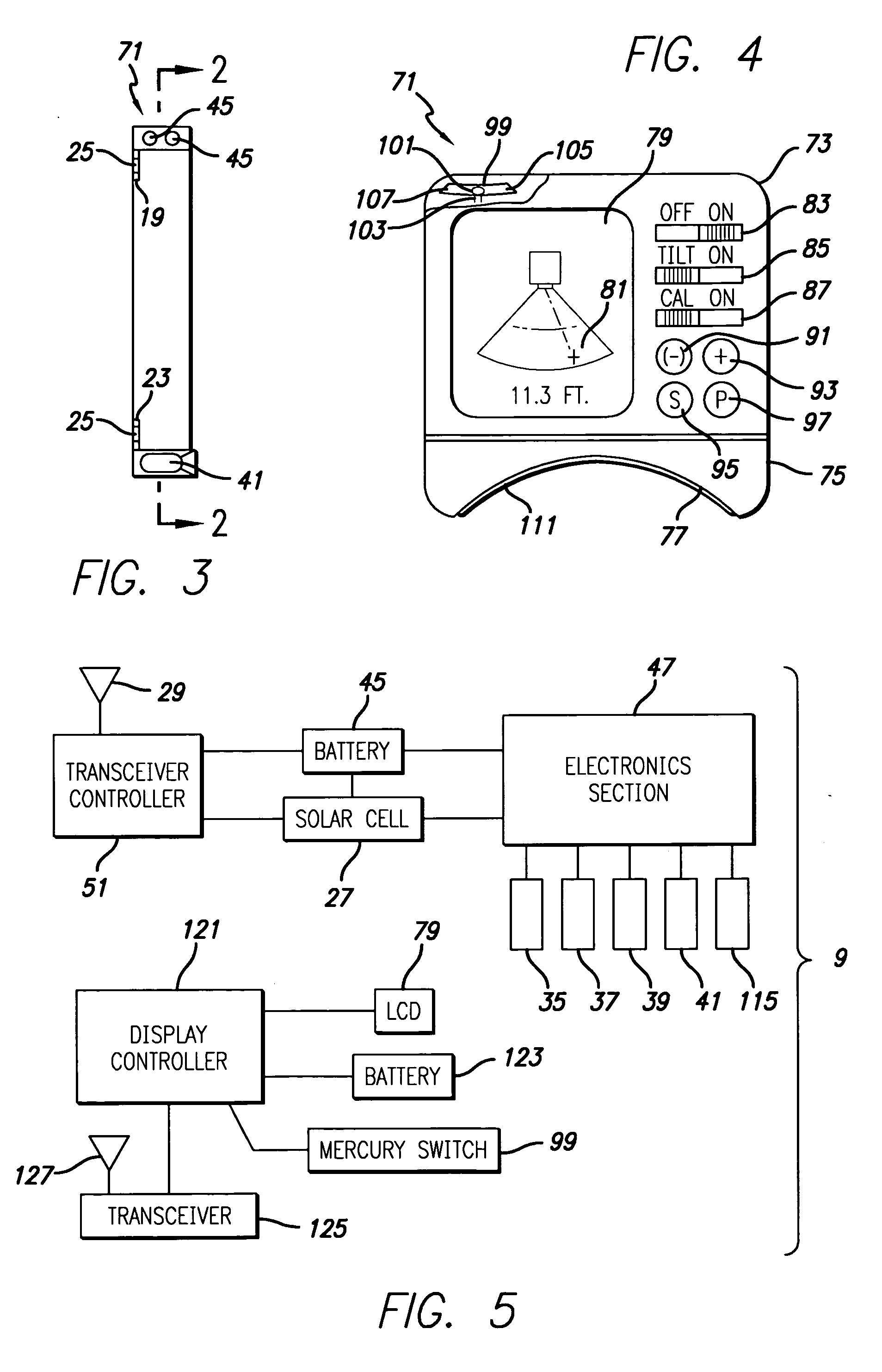
[0006] The reverse mode detection system provides an extremely inexpensive system which can be installed in seconds and which can be used by drivers to gauge the distance from the rear of the vehicle to an object, possible an array of objects, and to provide an optional combination of a soft alert or a distance reading which the user can optionally use to assist in reverse movements. One advantage of the system not before seen is some indication of the rear clearance space left available to the user in backing. Because of the different types of vehicles and the different configurations of the rear areas of vehicles upon which the system may be mounted, a calibration feature allows users to calibrate the unit especially with regard to the type of object which the user is likely to encounter most often.
[0007] As an example, where a driver needs to back into garage or a walled parking space, and especially the same space again and again, a readout can be calibrated based upon the placement of the automobile in a position in which the driver does not want to exceed and this position can be zeroed. Further, if this is one of three or four situations the driver is likely to encounter, he can store and retrieve the “zeroed” values for several such situations for maximum utility. Thus, where the driver wants to approach a wall in his work parking space, he can view the last foot or so of movement on his distance monitor and approach the optimum parking distance with precision.
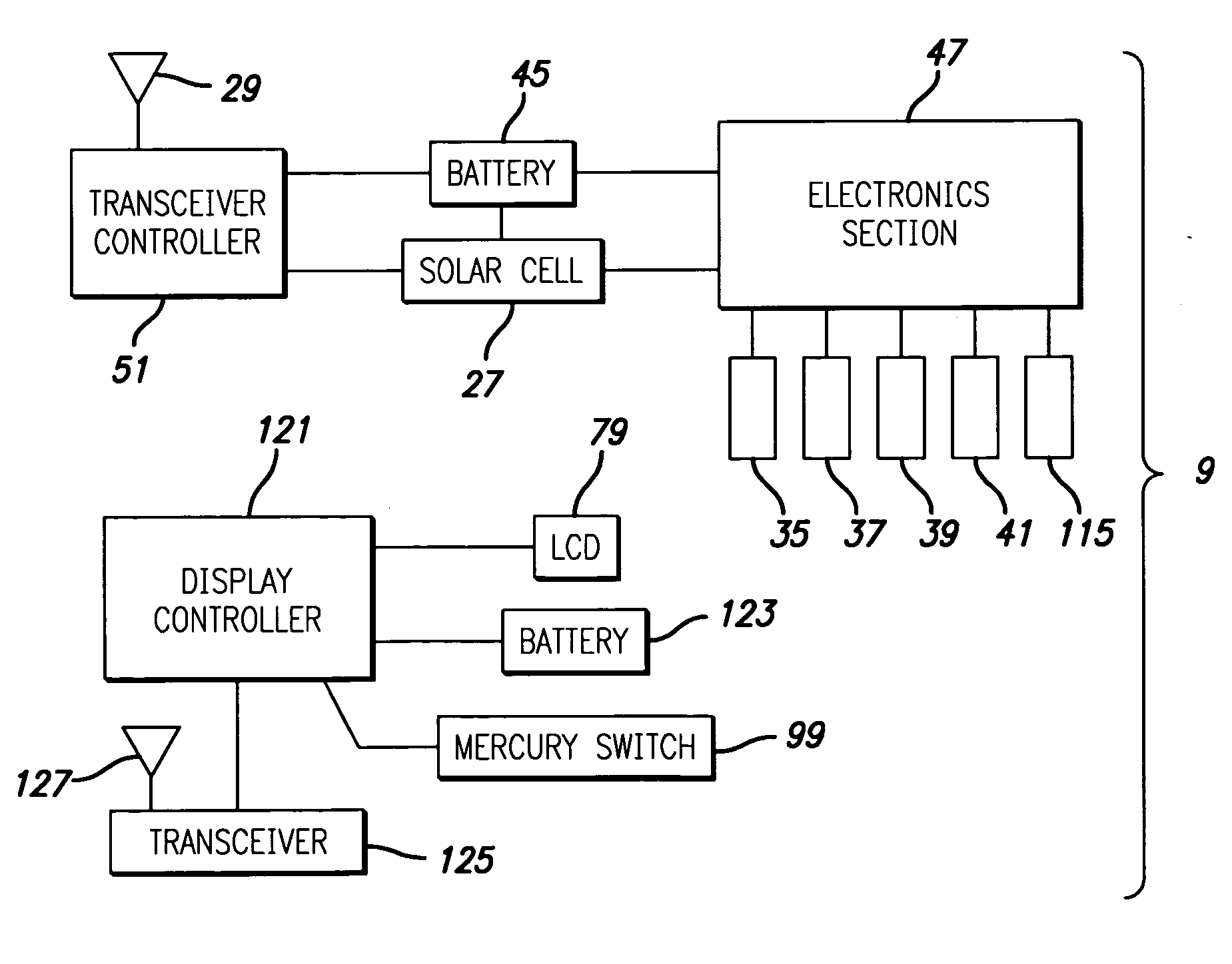
[0009] The frame structure contains batteries and electronics which will both power a distance measuring device as well as a transmitter to transmit the distance information to the user inside the automobile. This topography of use enables several advantageous modes of operation. Batteries may be saved by providing a switching logic based upon (1) driver control of the on / off rear frame sensor, (2) a reverse motion sensor, (3) a periodic “ping” signal to see if there is any objects in the immediate vicinity, and (4) an inactivity mode which may use a sensor to enable a long cutoff span of time during which the vehicle is parked and / or not running.

Problems solved by technology

Almost all of the systems attempt to override driver control, and like most extremely complex innovations, are more likely to add problems to automobile ownership and increase automobile down time than the advantages are worth.
The problem with this system is that the car may lock the brakes when passing a parked car on the side of the freeway.
This type of system has been fraught with problems, as no one who drives an automobile with this system would tolerate even one instance of a mis-triggering of an extreme stop on the freeway.
Even more importantly, the degree of sophistication of such devices and the degree of integration into the automobile system, the required compatibility along with the labor make the system technically prohibitive and cost prohibitive.
The problem has been combining the method of distance measurement, the level of integration and the degree of operator attention and override involved.
Integration into the braking system is impractical, but the degree of wiring and electrical integration remains problematic.
None of the above solutions for a driver give any real advantage.
Therefore, the focus has erroneously been placed upon control of the braking system and perhaps in providing distracting warnings.

Method used


Image

  • Vehicle reverse warning and distance measurement system
  • Vehicle reverse warning and distance measurement system
  • Vehicle reverse warning and distance measurement system

Examples


Embodiment Construction

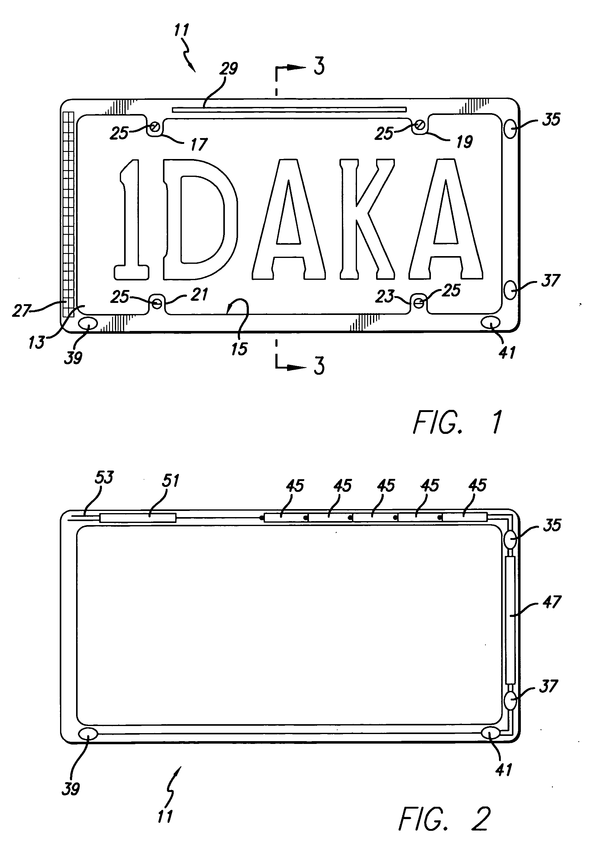
[0026] In general, automobile reverse warning and distance measurement system 9 is shown within a frame housing structure 11 is provided which can fit adjacent a vehicle's license plate which is shown in background as having the license number 1DAKA. The format shown is an American Automobile license plate format having a dimension of about six inches high by about twelve inches wide. Other formats can be used, including the European standard of a much wider and less high license plate shape.

[0027] The important element to note in FIG. 1, as well as the other drawings, is the accommodation of the space into which an automobile license plate 13, and thus the frame housing structure 11 must fit. In extreme cases, and for some vehicles, the license plate 13 fits into an area restricted on all four sides. In other cases the license plate 13 can have an upper restriction only or a lower restriction only. As a result, to insure that the frame housing structure 11 can be used in all confi...


PUM


Abstract

A reverse mode detection system provides an extremely inexpensive system which can be installed in seconds and which can be used by drivers to gauge the distance from the rear of the vehicle to an object, possible an array of objects, and to provide an optional combination of a soft alert or a distance reading which the user can optionally use to assist in reverse movements of an vehicle. One advantage of the system not before seen is some indication of the rear clearance space left available to the user in backing, and a multi storage calibration ability to enable more precise backing with regard to previously calibrated objects. The ability of the reverse warning and measurement system to actually be used on an vehicle with broad acceptance is based upon its mounting system, simplicity and energy sources which are self contained and conserving of power. The distance sensor is mounted in a frame shaped structure for attachment adjacent the license plate. The frame shaped structure will follow the license plate size which is typically a standard size for different countries. A transmitter associated with the reverse light wiring and illumination system can optionally activate the system in order to conserve battery power.

Description

FIELD OF THE INVENTION [0001] The present invention relates to the field of distance measurement and safe vehicle operation and more particularly to a user installable rearward looking distance measuring device with calibration which enables users to have an instant reading of the closeness of objects to the rear of a vehicle, while providing for installation by ordinary users. BACKGROUND OF THE INVENTION [0002] A number of systems have been available for safety and accident prevention in automobiles. Almost all of the systems attempt to override driver control, and like most extremely complex innovations, are more likely to add problems to automobile ownership and increase automobile down time than the advantages are worth. As an example, an attempt has been made to provide radar devices which prevent a sleepy driver from approaching a parked car at high speed on the freeway. The problem with this system is that the car may lock the brakes when passing a parked car on the side of t...

Claims


Application Information

Patent Timeline
Patent Type & Authority Applications(United States)
IPC IPC(8): G06F17/00
CPCB60R11/0235B60R11/04B60R13/10
Inventor MAH, PAT Y.
Owner DAKA RESEARCH INC
Learn More