Phono connector

Inactive Publication Date: 2016-01-07
NORDOST
View PDF7 Cites 0 Cited by
  • Summary
  • Abstract
  • Description
  • Claims
  • Application Information

AI Technical Summary

Benefits of technology

The invention is a connector that allows for the secure and reliable grounding of wires to a central signal terminal. The connector features a front conductive ground mating ring that ensures maximum retention force with the mating connector. The overall design maintains coaxial type grounding design around a central signal conductor pin, improving signal distortion and reducing interference. The connector is easy to install and remove, and includes a removable center signal pin that prevents shorting to the grounding termination ring. A resonator ground conductor is positioned between the housing and the insulating sleeve for grounding. The result is a connector that ensures reliable grounding and improved signal quality.

Problems solved by technology

RCA plug designs have been criticized by electrical engineers in the audio and other electrical disciplines.
Additionally, after many mating and un-mating cycles, the thin cylindrical slotted retaining ring of an original RCA plug and socket loses its spring temper, creating a poor electrical connection.
This results in noise and high electrical resistance, due to the reduction of the mating forces.
However many manufacturers of the RCA socket have not always precisely designed or manufactured to these dimensions.
In the termination area on a typical RCA plug, there is the potential for electrical shorting of the center pin wire(s) to the outer ring wire(s) due to mutable wires, braid or large solder joints.
When using an RG coaxial cable type in the typical RCA plug, the braid is twisted into a single stranded conductor which is then soldered to the connector creating the potential for electrical shorting to the center pin that is exposed in the solder termination area.

Method used


Image

  • Phono connector
  • Phono connector
  • Phono connector

Examples


Embodiment Construction

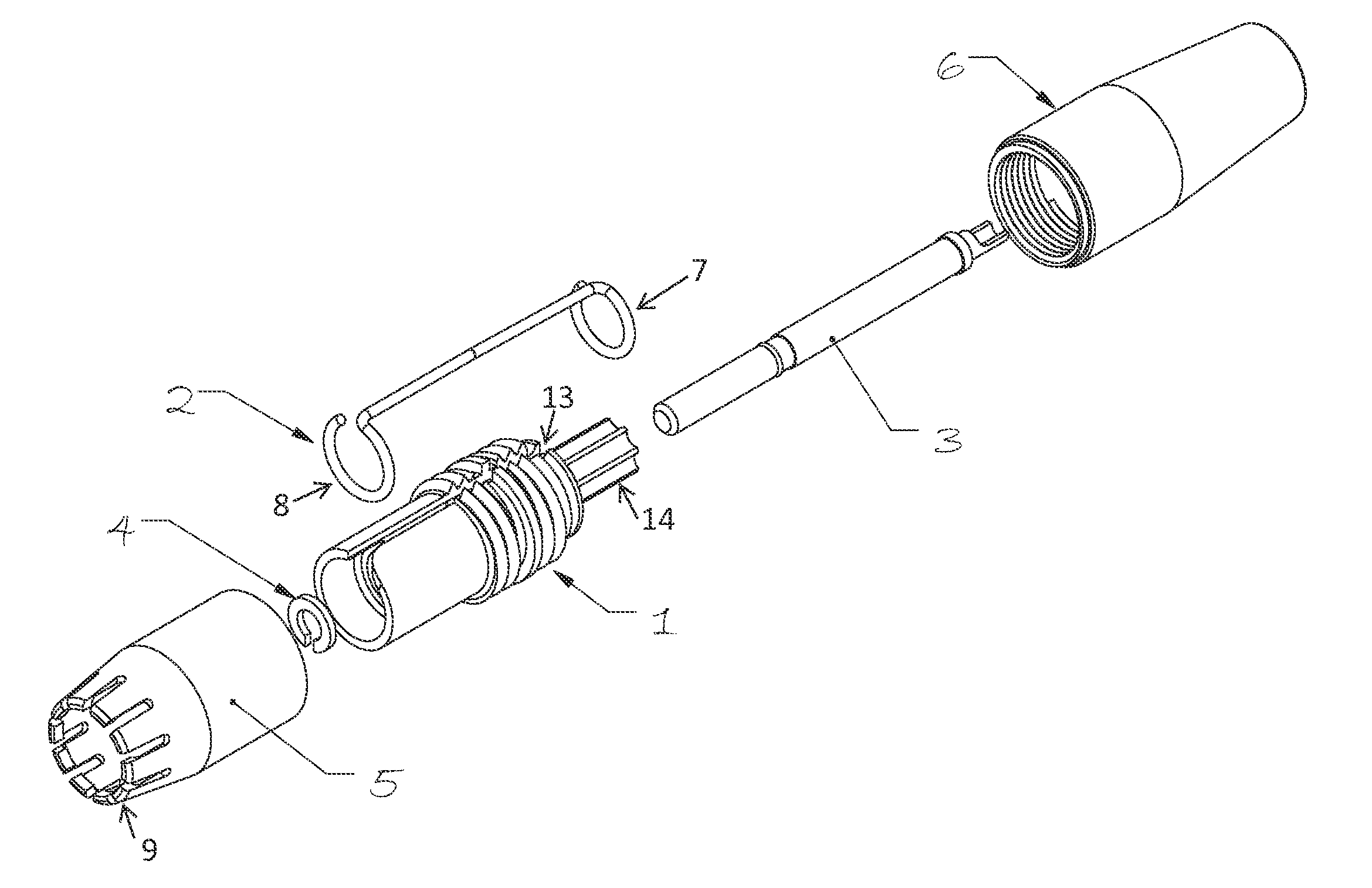
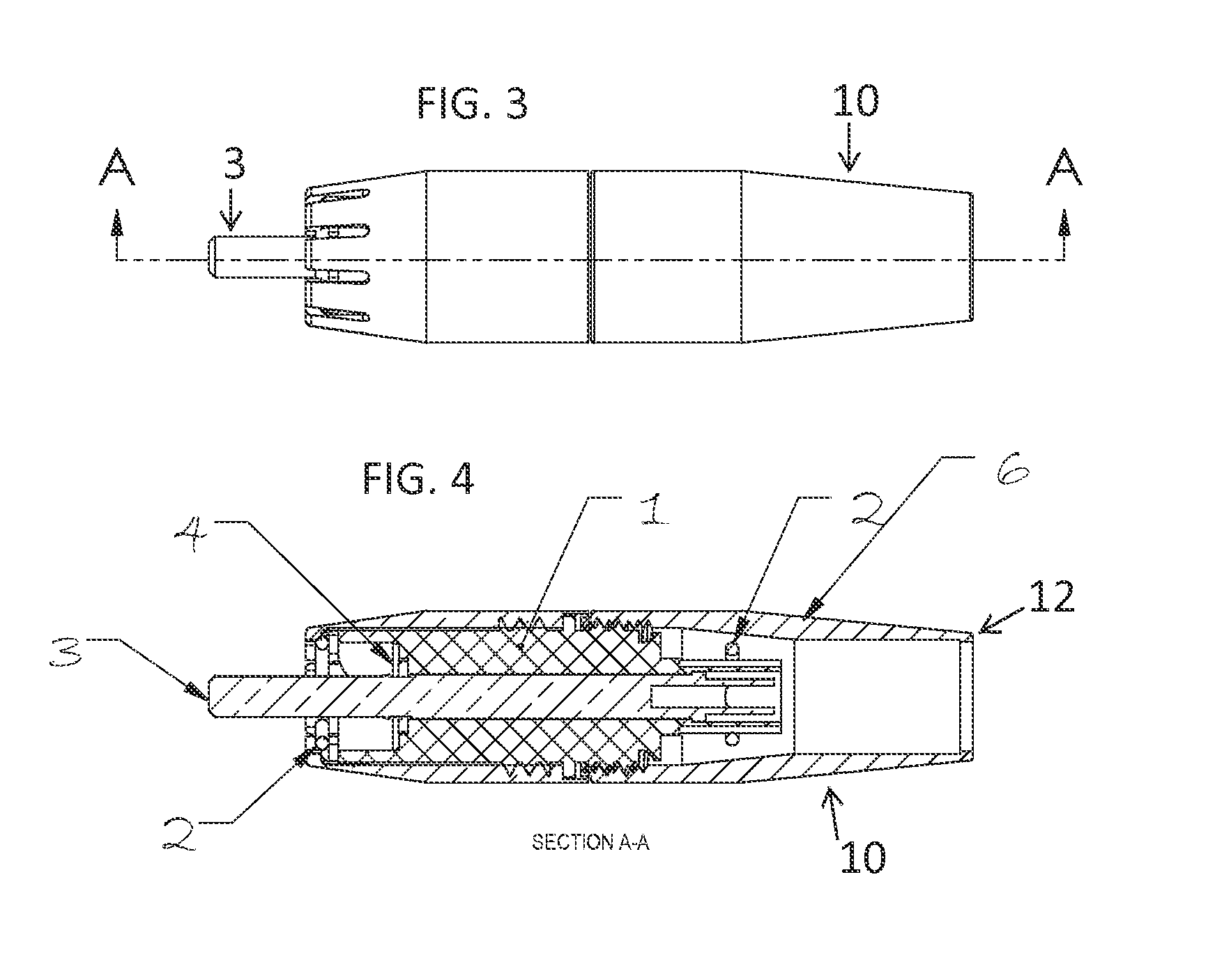
[0017]The phono connector (10) shown in FIGS. 1 through. 4 addresses the problems described above. The connector generally comprises a front cover or shell (5), a rear cover or housing (6) and a central signal pin (3).

[0018]The front connector shell or housing (5) is adopted to mate with an electrical phono-type socket (not shown) and is made from a bronze spring type material for a robust design.

[0019]The rear metallic cover or housing (6) is designed with a cable stop (12) that is used as a cable jacket strain relief when used in conjunction with a hog type crimp ring.

[0020]A center signal pin (3) carries signals from the conductor wires and is adopted to mate with an electrical phono-type socket (not shown). The center signal pin (3) is coaxial with the front and rear housings (5, 6).

[0021]A resonator ground conductor is made from a phosphorous bronze alloy. The resonator ground. conductor (2) has a ground 360° termination ring (7) on the same plane as the soldered connector wire...


PUM


Abstract

A co-axial electrical connector having an outer shell and a co-axially positioned center signal pin with a resonator ground conductor.

Description

CROSS-REFERENCE TO RELATED APPLICATION[0001]This application claims the benefit of U.S. Provisional Application No. 61 / 821,025, filed May 8, 2013.FIELD OF THE INVENTION[0002]This invention relates to plug connectors, consisting of a center signal pin and an outer shell, which are widely used for electrical connections. These connectors commonly are referred to as “RCA Connectors.”BACKGROUND OF INVENTION[0003]An RCA phono-type plug mates with an RCA phono-type socket. RCA plug designs have been criticized by electrical engineers in the audio and other electrical disciplines.[0004]The typical RCA plug connector has no latching mechanism to secure the plug to its mating socket. Additionally, after many mating and un-mating cycles, the thin cylindrical slotted retaining ring of an original RCA plug and socket loses its spring temper, creating a poor electrical connection. This results in noise and high electrical resistance, due to the reduction of the mating forces. The original RCA so...

Claims


Application Information

Patent Timeline
IPC IPC(8): H01R13/625H01R9/05
CPCH01R13/625H01R9/0527H01R24/38H01R13/65917H01R13/65914
Inventor REYNOLDS, JOSEPH M.MITCHELL, WILLIAM D.
Owner NORDOST
Why Eureka
Try Eureka