
Corded lattice based floating photovoltaic solar field with independently floating solar modules

a solar module and solar field technology, applied in photovoltaics, solar heat collectors for particular environments, heat collector mounting/support, etc., can solve the problems of weak link breakage, system of any appreciable size may not withstand the action of waves and wind, and achieve flexibility and a degree of freedom of movemen

Inactive Publication Date: 2016-01-07
SOLARIS SYNERGY ISRAEL
View PDF3 Cites 14 Cited by
  • Summary
  • Abstract
  • Description
  • Claims
  • Application Information

AI Technical Summary

Benefits of technology

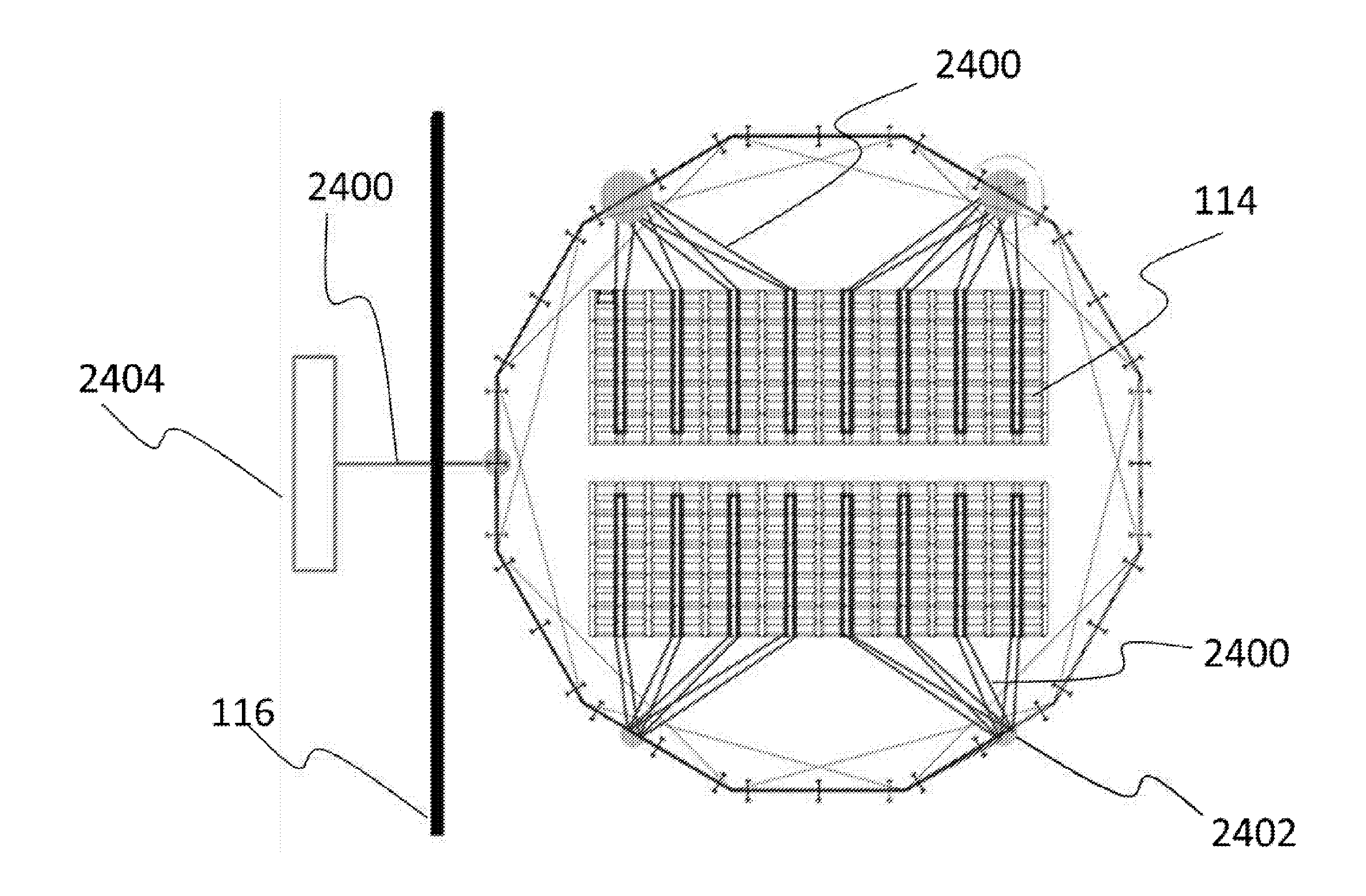
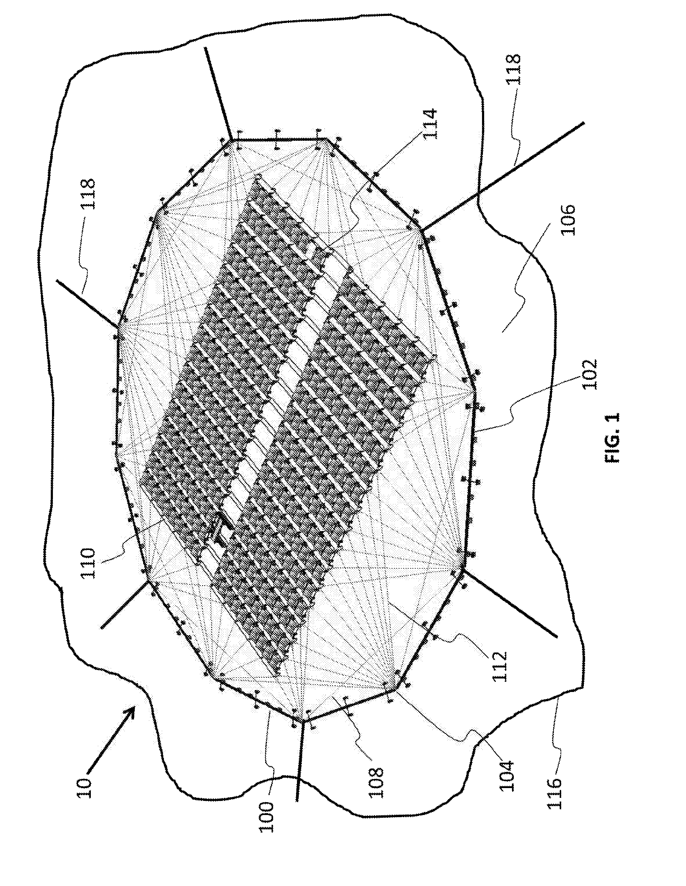
The present invention is a system of solar-electric modules that can be placed on the surface of a water body and move with the waves and wind. The system is designed to maintain its shape and integrity while still allowing flexibility and adjustment to the changes in the wind and sea levels. In addition, each solar module is tilted to reduce wind resistance, which means that the module can adjust its angle of tilt relative to the horizon, resulting in improved efficiency and reduced wear and tear without the need for external controls or power. This design is better than existing systems because it allows for greater flexibility and response to environmental forces.

Problems solved by technology

These types systems are disadvantageous because they require inter alia a) a large quantity of materials which may complicate the assembly process and make installation expensive and b) significant strengthening of the structure and the anchoring mechanism due to the accretion of wind-generated drag and elevation forces on the system.
However such a system of any appreciable size may not withstand the action of waves and wind.
Wind loads on the modules will accumulate causing weak links to break, while wave action may cause the floating carpet to deform.
Placing the floating carpet under tension may either break the connections between the modules or the modules themselves.

Method used


Image

  • Corded lattice based floating photovoltaic solar field with independently floating solar modules
  • Corded lattice based floating photovoltaic solar field with independently floating solar modules
  • Corded lattice based floating photovoltaic solar field with independently floating solar modules

Examples


Embodiment Construction

[0062]It is appreciated that certain features of the disclosure, which are, for clarity, described in the context of separate embodiments, may also be provided in combination in a single embodiment. Conversely, various features of the present disclosure, which are, for brevity, described in the context of a single embodiment, may also be provided separately or in any suitable combination or as suitable in any other described embodiment of the invention. Certain features described in the context of various embodiments are not to be considered essential features of those embodiments, unless the embodiment is inoperative without those elements.

[0063]Although the disclosure has been described in conjunction with specific embodiments thereof, it is evident that many alternatives, modifications and variations will be apparent to those skilled in the art. Accordingly, it is intended to embrace all such alternatives, modifications and variations that fall within the spirit and broad scope o...


PUM


Abstract

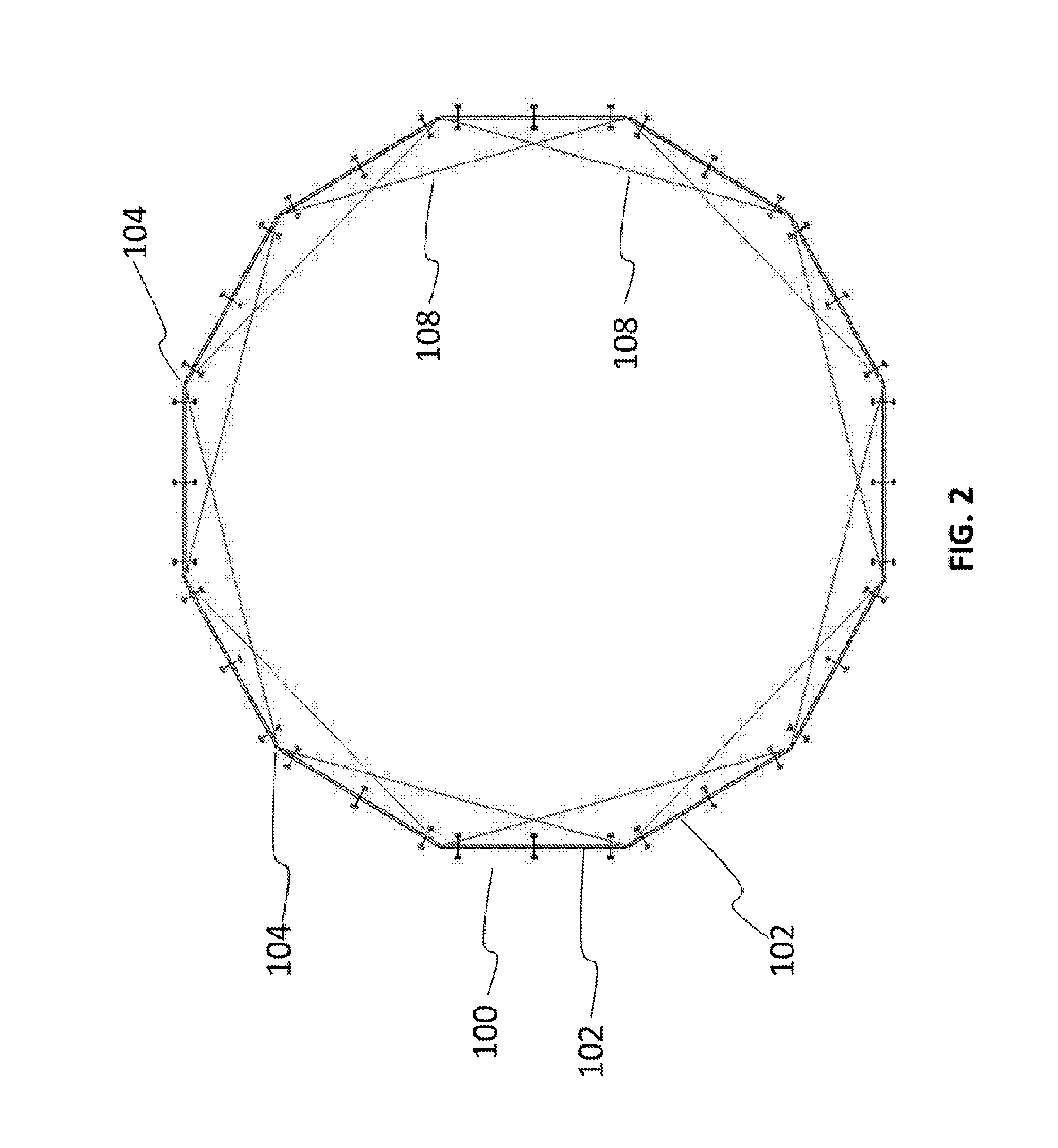
Provided herein is a floating photovoltaic solar device designed to reduce the effect of wind forces without the use of external control or power. The device includes a floating anchored frame with a means for connecting an internal corded lattice; a corded lattice suspended within the floating frame and forming a set of polygonal cells in which independently floating solar photovoltaic modules are positioned. Access for scheduled and unscheduled maintenance may be provided by a floating service gantry. The system is modular and several devices may be connected in a honeycomb-like structure.

Description

CROSS-REFERENCE TO RELATED APPLICATIONS[0001]The present application claims priority to U.S. Provisional Application Ser. No. 61 / 851,403 filed Mar. 7, 2013 and entitled “A Guy-Wire Based Floating Photovoltaic Solar Field With Floating Solar Panels” the entire contents of which are incorporated by reference herewith.FIELD AND BACKGROUND OF THE INVENTION[0002]In existing floating photovoltaic systems, the solar modules are rigidly fixed on an anchored floating platform, a rigid or semi-rigid anchored floating framework, or an anchored platform made up of interconnected floating rafts. These types systems are disadvantageous because they require inter alia a) a large quantity of materials which may complicate the assembly process and make installation expensive and b) significant strengthening of the structure and the anchoring mechanism due to the accretion of wind-generated drag and elevation forces on the system.[0003]In principle one could take a solar module, place it on floats, a...

Claims


Application Information

Patent Timeline
Patent Type & Authority Applications(United States)
IPC IPC(8): H02S40/36H02S10/40H02S20/30H02S40/10
CPCH02S40/10H02S10/40H02S20/30H02S40/36B63B1/121B63B59/06B63B2035/4453F24S20/70F24S25/12F24S25/50F24S25/70F24S30/40F24S40/85Y02E10/47Y02E10/50
Inventor KOKOTOV, YURIFISHER, YOSSICAINE, SHLOMO
Owner SOLARIS SYNERGY ISRAEL
Learn More