Composite flexible and conductive catheter electrode

a flexible, conductive and catheter technology, applied in the field of electrophysiological catheter electrode bands, can solve the problems of limiting the flexibility of the catheter, the inability of the catheter to reach a desired area, and the possibility of rigid metal bands sliding off the catheter, and being lost inside the patien

Inactive Publication Date: 2007-10-25
KEENAN ERICK
View PDF7 Cites 49 Cited by
  • Summary
  • Abstract
  • Description
  • Claims
  • Application Information

AI Technical Summary

Benefits of technology

[0023] The general concept of the composite flexible and conductive band is that each of its components uses their individual properties to perform a specific function and then they, with synergy, combine to meet the functional requirements of a 2 to 14 French diameter flexible conductive band electrode. The flexible (polymer / elastomer) component gives the band variable flexibility, supports the position of the conductive component, locks the conductive component safely into the band, attaches the band securely to the catheter tube, hermetically seals the conductor wire, can include a radiopaque material, and can be colored to allow for visual identification of the band or give pleasing aesthetics. The conductive component (a thin metal piece) is designed to possess an anisotrotic strength in the desired direction and not in an undesired direction, thus allowing flexibility in the required direction. The conductive component's primary functional demand is the ability to carry electrical current continuously without interruption from the connector wire onto the surface of the electrode band contacting the patient's tissue. While the previous statements describe the band components that are the mandatory base parts to accomplish a functional composite flexible and conductive electrode band, an added benefit of this invention is the ability to incorporate enhancements. Features such as a thin electroplated platinum surface onto the outside of the band is one example.
[0024] The invention of the composite flexible and conductive band succeeds over the following shortcomings and technical difficulties in some other methods of prior band design construction and manufacture for cardiac catheters. Flexibility of the electrode band and the catheter's distal tip can be better than that of the other methods, due to this invention's use of delineated functional propose. This specific use allows the utilization of the flexible component 100% for flexibility and the conductor component 100% for electrical requirements, without one component effecting the other one's functionality. Although each component performs its task independently, it is by efficient design that some components are not just neutral in a function, but aid in helping the band's performance. An example is how that the conductive component is designed to be anisotropic, so as not to impair the performance of the flexible component in its functionality.
[0025] Electrical current is uninterrupted and has no spark gaps. This is ensured by the conductive component's continuous one-piece design that connects the conductor wire and the outer surface of the electrode band without breaks or reliance on just touching.
[0027] The invention has superior resistance to electrically induced polymer bond failure due to the fact the flexible component (the polymer) is not stressed into a dual role use, as the adhesive conductive bands are. The adhesive needs to act both as a tight bonding agent to attach the band onto the tube and hold onto the conductive powder, while also performing the task of an elastomer to give the band its flexibility.
[0028] This invention also allows for precise band placement control down to a space of 0.020″ between conductive bands, conductive band thickness as small as 0.0005″, a method of safety locking the conductive element into the band, and a hermetically seal from fluid intrusion into the catheter inner lumens.
[0029] Construction methods used to produce this invention are of a low technology in art and can be performed with simple low cost tools by technicians of moderate abilities and training. The simple design of the composite flexible and conductive electrode bands and their attachment onto a catheter lends itself to the potential for a large degree of automated tooling to produce them. Another advantageous feature of this invention is the use of economical materials which are readily available from a wide source of suppliers, in the construction of the band electrode.

Problems solved by technology

This method of construction has some technical and design drawbacks.
Rigid metal bans limit catheter flexibility and make the ability of the catheter to reach a desired area impossible.
Rigid metal bands have the possibility of sliding off the catheter and being lost inside the patient.
This can cause trauma due to abrasions.
This can cause loss of signal and sterility issues.
Rigid metal band configuration (number and length of bands) and spacing between bands is also a problem.
By trying to place bands less the one millimeter apart, difficulties are experienced in the manufacturing and performance of the catheter.
This colloidal suspension matrix is flexible and thus allows for longer bands and better placement of the catheter's electrodes onto the required tissue wall; but it also has some design weaknesses:
The resulting problems are intermittent signal and spark gap across the conductive particles.
Another potential problem is the loss of conductive particles into the patient's blood stream.
Manufacturing issues are presented, such as the control of accuracy of the band's placement, the uniformity of the band's thickness, and control of the chemical science which relates to the polymer's adhesive and cohesive properties between not only the conductive particles and adhesive polymer, but also the adhesive polymer and the catheter's polymer tube.
Electrical current distribution could also be random and difficult to control because of the varied powder's distribution pattern throughout the inner wall, middle sections and onto the outer surface of the conductive adhesive bands.
Basically this concept is still a rigid metal band and therefore many of the problems which occur in rigid metal bands still occur in the slotted metal bands, or are sometime compounded due to the slots.
This problem has been increased with the slotted metal bands because of its multiple possible abraiding corners.
The slots also may harbor foreign matter if not thoroughly cleaned.
This method of band construction also gives flexibility but suffers from the need for special tooling and a higher degree of manufacturing process control.
The joints between the coil loops may also harbor foreign matter if not thoroughly cleaned.
This metal band is flexible, but the nature of the material is such that, over time, flexing of the metal will cause stress cracks leading to band to failure.
This method has some difficulties in its manufacturing process, e.g. it requires a high degree of technology and the catheter's distal tip must be completely assembled prior to the thin film application.

Method used


Image

  • Composite flexible and conductive catheter electrode
  • Composite flexible and conductive catheter electrode
  • Composite flexible and conductive catheter electrode

Examples


Embodiment Construction

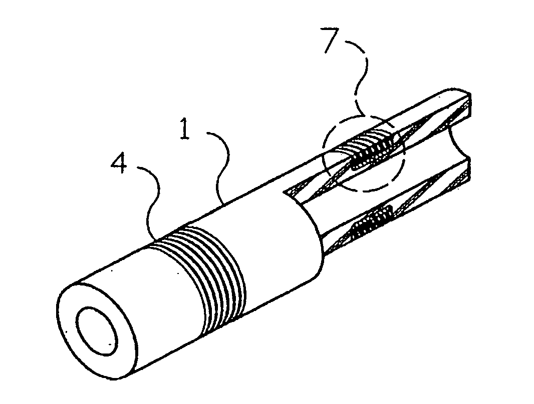
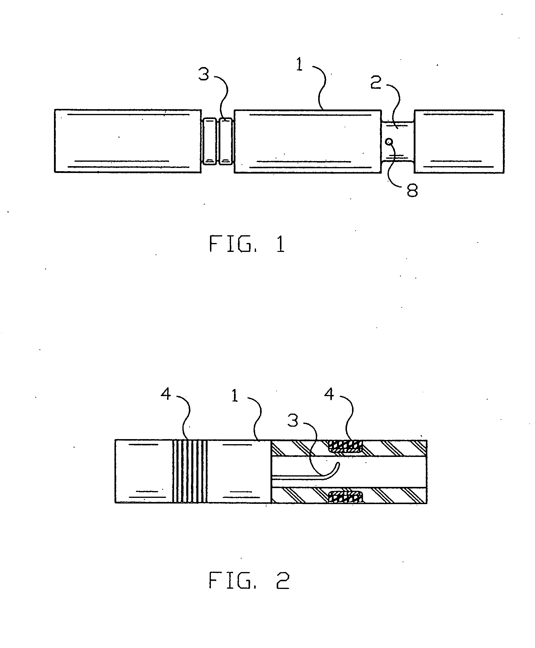
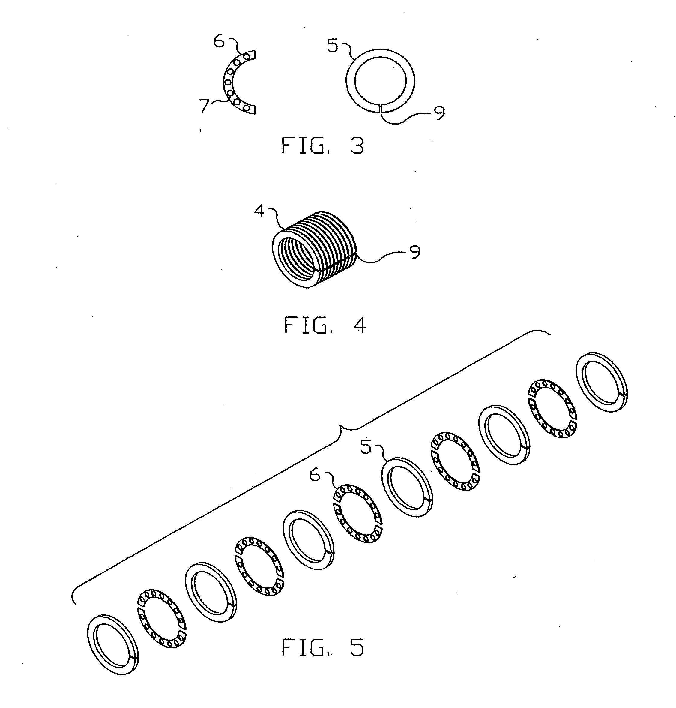
[0038]FIG. 4 illustrates an assembled composite flexible and conductive electrode band 4 shown in perspective view before its assembly onto a cardiac catheter tube 1, where it performs the function of an electrode. The cylindrically shaped band 4 is a composite composed of flexible, ring shaped elements 5 and of ring shaped conductive elements 6, which are shown in FIG. 3. These component elements are arranged in an alternating pattern of flexible elements 5 and conductive elements 6 in the manner as shown in the exploded perspective illustration in FIG. 5. Uninterrupted electrical currents are carried from inside hole 8 through the wall in wire groove 2 to the outside surface of the band 4 by means of conductive element 6. Conductive element 6 is made from a thin metal (examples are gold, platinum, silver, stainless steel, platinum / iridium alloy, plated cooper or other suitable metal) sheet between 0.0005″-0.150″ in thickness, from which the shape that is shown in FIG. 3 is die sta...


PUM

PropertyMeasurementUnit
flexibleaaaaaaaaaa
widthaaaaaaaaaa
conductiveaaaaaaaaaa

Abstract

A flexible cardiac catheter for sensing electrical activity within and administering therapy to a patients' heart has a series of flexible, conductive electrode bands positioned in grooves in the catheter's tubular body. The bands consist of alternating flexible and conductive elements, providing flexibility and overall versatility to the catheter. The electrode bands have controllable flexibility due to the elastic properties of the flexible elements and continuous uninterrupted electrical current conductance from the one-piece design of the conductive element. The synergy of the components of the composite flexible and conductive bands will help solve problems current electrode bands have and will allow for a freedom in the design of catheter electrode band configurations in the future.

Description

RELATED APPLICATION [0001] This application is a continuation-in-part of U.S. application Ser. No. 10 / 367,034.BACKGROUND OF THE INVENTION [0002] 1. Field of Invention [0003] This invention relates to the electrophysiological catheter electrode band used in the mapping (measurement of electrical potential), pacing (stimulation of the muscle tissue by pulsing an electrical current), and ablating (burning the tissue by use of high electrical current) of the heart's inner wall. This invention generally relates to catheters and leads used in sensing electrical activity within a patient and administering therapy, and more particular to such catheter and leads incorporating band electrode configured for flexibility and tractability within the body. [0004] 2. Discussion of Related Art [0005] A method of construction of a conductive band electrode is typically now accomplished by using a rigid thin wall, metal tube (example: platinum / iridium alloy, stainless steel) band which is swaged or ad...

Claims


Application Information

Patent Timeline
Patent Type & Authority Applications(United States)
IPC IPC(8): A61B5/042A61N1/05
CPCA61N1/05A61N1/056Y10T428/1352Y10T428/139Y10T428/1303Y10T428/1355Y10T428/13Y10T428/1359
Inventor KEENAN, ERICK
Owner KEENAN ERICK
Why Eureka
Try Eureka