Automatic pet feeder

Active Publication Date: 2016-01-14
TONGFU MFG
32 Cites 28 Cited by

AI-Extracted Technical Summary

Problems solved by technology

Such a technical solution is a solution which is relatively simple and more popular but is prone to get stuck.
When the food reaches the bottom of the container in the shape of an inverted cone, it is easy to form a stable structure, i.e., a stuck state, due to interaction of gravity and friction between the food, and it is more prone to get stuck especially when the food is irregular in appearance or bigger in particle size.
When the blades on the inner cylinder rotate, in order to overcome pressure and friction caused by upper food, it is also prone to get stuck.
In addition, hard blades may get stuck because the food is clamped, and in order to solve the problem, when the blades are made of a soft material, there is a possibility that the space between the blade groups changes significantly, but the problem of inaccurate feeding quantity arises.
As stated above, lots of users of the automatic feeder reflect that the feeder has design defects, and problems such as the food leaking mechanism gets stuck and food leakage quantity is uncontrollable may occur.
In addition, the following problems may also ...

Method used

[0040]On the basis of Embodiments 1-5, it is further disclosed that a partition ridge 14 may be further provided, where the partition ridge 14 is disposed ...

Benefits of technology

[0020]The positioning ridge is a plate-like structure with a certain thickness and is fixed at a recess of adjacent positioning teeth, and in order to cooperate with the structure, a recess between two ad...

Abstract

The present invention relates to pet supplies and to an automatic pet feeder. Food is prone to get stuck in a current automatic pet feeder to cause ineffective feeding, an automatic pet feeder is provided, the feeder includes a food leaking component and a feeding tray; the food leaking component includes a cylindrical rotating shaft located in the center, and a big-end-down food leaking outer wall, where a grid is fixed between an outer side surface of the rotating shaft and the food leaking outer wall, and the grid is radial with the axis of the rotating shaft as the center of a circle, to partition a space between the outer side surface of the rotating shaft and the food leaking outer wall into feeding spaces with the same size.

Application Domain

Animal feeding devicesPisciculture and aquaria

Technology Topic

Mesh gridEngineering +1

Image

  • Automatic pet feeder
  • Automatic pet feeder
  • Automatic pet feeder

Examples

  • Experimental program(6)

Example

Embodiment 1
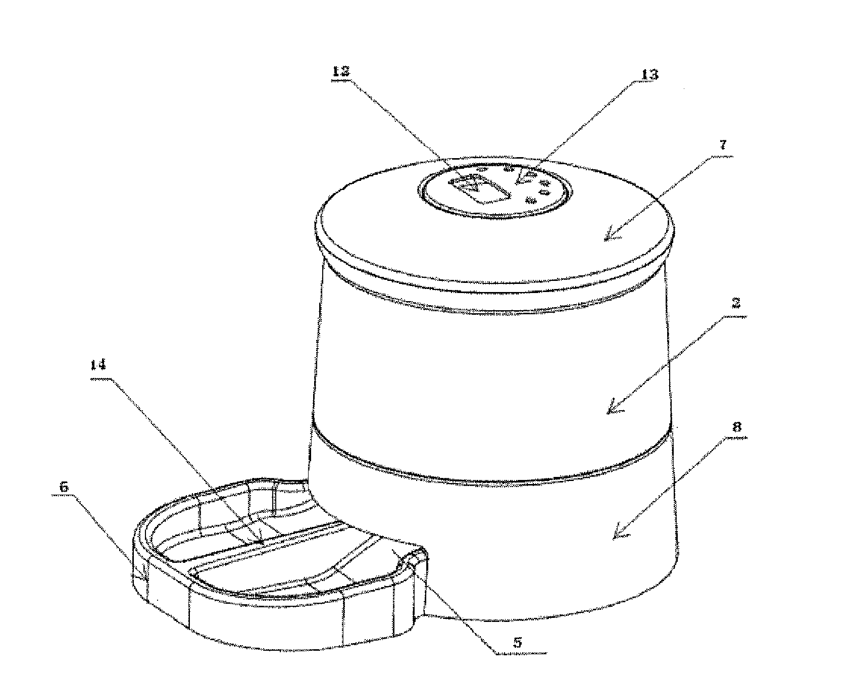
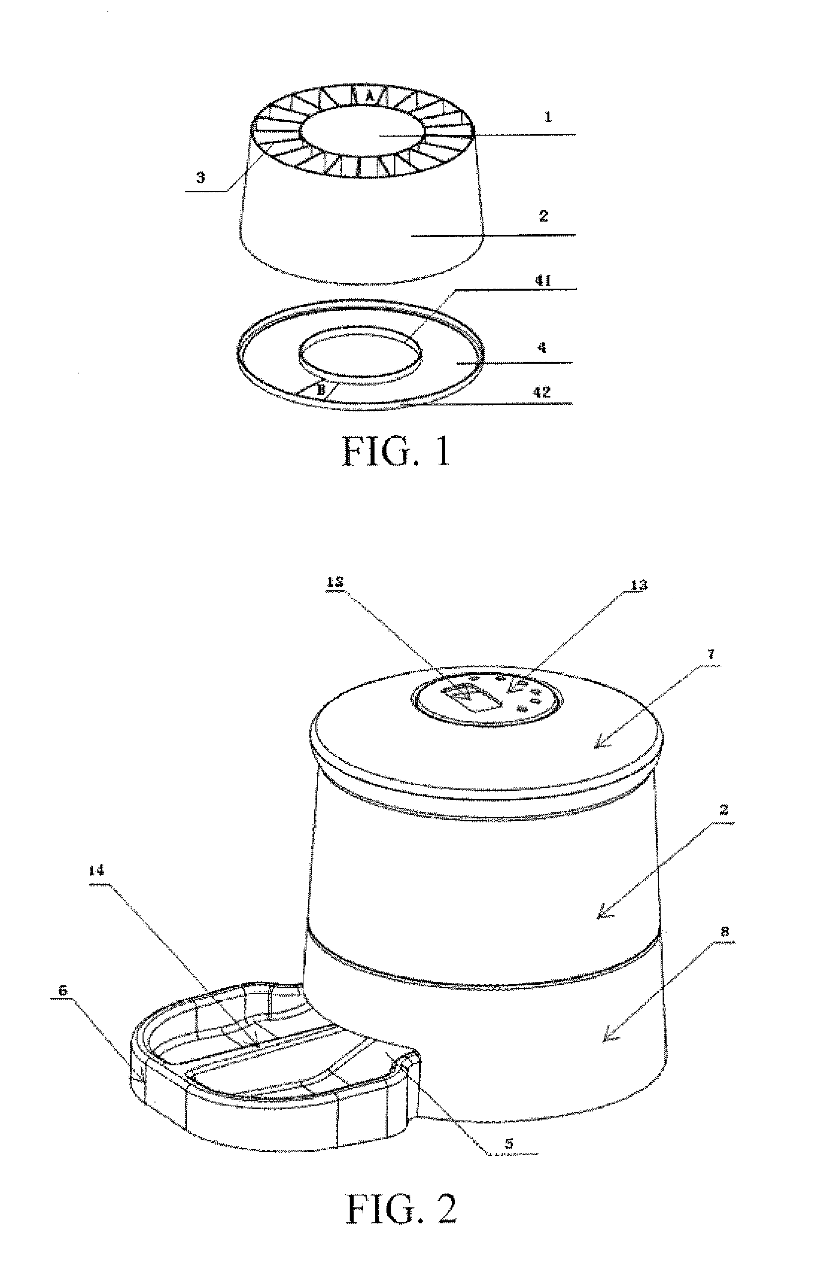
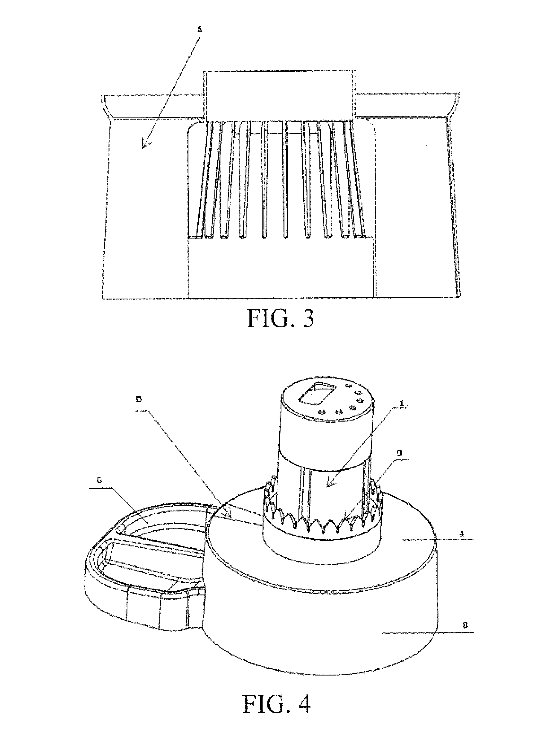
[0032]FIG. 1, FIG. 2 and FIG. 3 show an automatic pet feeder, where the feeder includes a food leaking component and a feeding tray; the food leaking component includes a cylindrical rotating shaft 1 located in the center, and a big-end-down food leaking outer wall 2, where a grid 3 is fixed between an outer side surface of the rotating shaft and the food leaking outer wall, and the grid 3 is radial with the axis of the rotating shaft as the center of a circle, to partition a space between the outer side surface of the rotating shaft and the food leaking outer wall into feeding spaces (A in the figures) with the same size, from which it can be seen that, due to the structure of the food leaking outer wall 2, the feeding spaces A are also big-end-down conical spaces, as those shown in FIG. 3; and further includes an annular food leaking plate 4 whose inner diameter is the same as the radius of the rotating shaft and outer diameter is the same as the radius of a lower rim of the food leaking outer wall, where an inner rim and an outer rim of the food leaking plate 4 expand upwards respectively to form an inner side limiting edge 41 and an outer side limiting edge 42, and the food leaking plate 4 is further provided with a sectorial food leaking hole (part B in the figures). The feeding tray consists of a chute 5 and a food tray 6, and is provided thereon with a rotating shaft mounting slot corresponding to the rotating shaft of the food leaking component, so as to form the structure as described in FIG. 2. It can be seen that a control panel 13 with a liquid crystal display 12 is disposed on the top of the rotating shaft 1.
[0033]The cylindrical rotating shaft 1 and the grid 3 as well as the food leaking outer wall 2 are fixed together to form an overall structure, a motor structure disposed inside the cylindrical rotating shaft 1 drives the food leaking component to rotate relative to the food leaking plate, reference can be made to the rotating technology in the prior art for this part, and leakage of food is implemented at the sectorial food leaking hole B, to achieve feeding effects.

Example

Embodiment 2
[0034]On the basis of Embodiment 1, by paying special attention to FIG. 4 and FIG. 5, a base 8 is further included, where the base is an annular box with a cavity, whose inner diameter matches the outer diameter of the rotating shaft 1, and is mounted and fixed to a lower end of the rotating shaft 1, an opening on one side thereof is available for insertion of the feeding tray, and the food leaking plate 4 matches the annular box, to close an upper top surface of the annular box.
[0035]Preferably, on the basis of this structure, it is further disclosed in this embodiment that positioning teeth 9 are further included, where the positioning teeth 9 are rotatably fixed to an upper rim of an inner circle of the base 8, a grid inner ring 10 is added correspondingly, the grid 3 is located between the grid inner ring 10 and the food leaking outer wall 2, a non-grid fixing side of the grid inner ring 10 projects to form positioning ridges 11, and the positioning ridges 11 match the positioning teeth 9, as that shown in FIG. 6.

Example

Embodiment 3
[0036]On the basis of Embodiment 1 or Embodiment 2, the area of the food leaking hole is greater than that of a sectorial cross-section of the feeding spaces.

PUM

no PUM

Description & Claims & Application Information

We can also present the details of the Description, Claims and Application information to help users get a comprehensive understanding of the technical details of the patent, such as background art, summary of invention, brief description of drawings, description of embodiments, and other original content. On the other hand, users can also determine the specific scope of protection of the technology through the list of claims; as well as understand the changes in the life cycle of the technology with the presentation of the patent timeline. Login to view more.

Similar technology patents

Stamping equipment applied to motor rotor punching sheet production

Owner:SHENGZHOU LIDA ELECTRIC APPLIANCES FACTORY

Method for recycling manganese ion in electrolytic manganese production tail end wastewater

InactiveCN101838064AImprove stabilityReduce the number of operators
Owner:CHINESE RES ACAD OF ENVIRONMENTAL SCI

Coverage rate test processing method and device and coverage rate test server and system

ActiveCN103095518AImprove stabilityReduce the probability of failure
Owner:ALIBABA GRP HLDG LTD

Classification and recommendation of technical efficacy words

Why Eureka
Try Eureka