Method for Downhole Cutting of At Least One Line Disposed Outside and Along a Pipe String in a Well, and Without Simultaneously Severing the Pipe String

Active Publication Date: 2016-01-14
HYDRA SYST
View PDF0 Cites 13 Cited by
  • Summary
  • Abstract
  • Description
  • Claims
  • Application Information

AI Technical Summary

Benefits of technology

[0010]Another object of the invention is to provide a method rendering possible, within a longitudinal section of a well, to sever one or more lines disposed outside and along a pipe string in a well, and without simultaneously severing the pipe string. By so doing, the pipe string does not need to be pulled out of the well, whereby the pipe string also maintains integrity, in terms of strength, within said longitudinal section.
[0011]Further, it is an object to use the present method for severing of said at least one line, and as an introductory measure before temporary or perma

Problems solved by technology

Upon such cementation, however, continuous lines disposed in an annulus along a pipe string may constitute leakage channels for pressurized fluids residing in the well.
If such leakage chan

Method used


Image

  • Method for Downhole Cutting of At Least One Line Disposed Outside and Along a Pipe String in a Well, and Without Simultaneously Severing the Pipe String
  • Method for Downhole Cutting of At Least One Line Disposed Outside and Along a Pipe String in a Well, and Without Simultaneously Severing the Pipe String
  • Method for Downhole Cutting of At Least One Line Disposed Outside and Along a Pipe String in a Well, and Without Simultaneously Severing the Pipe String

Examples


Embodiment Construction

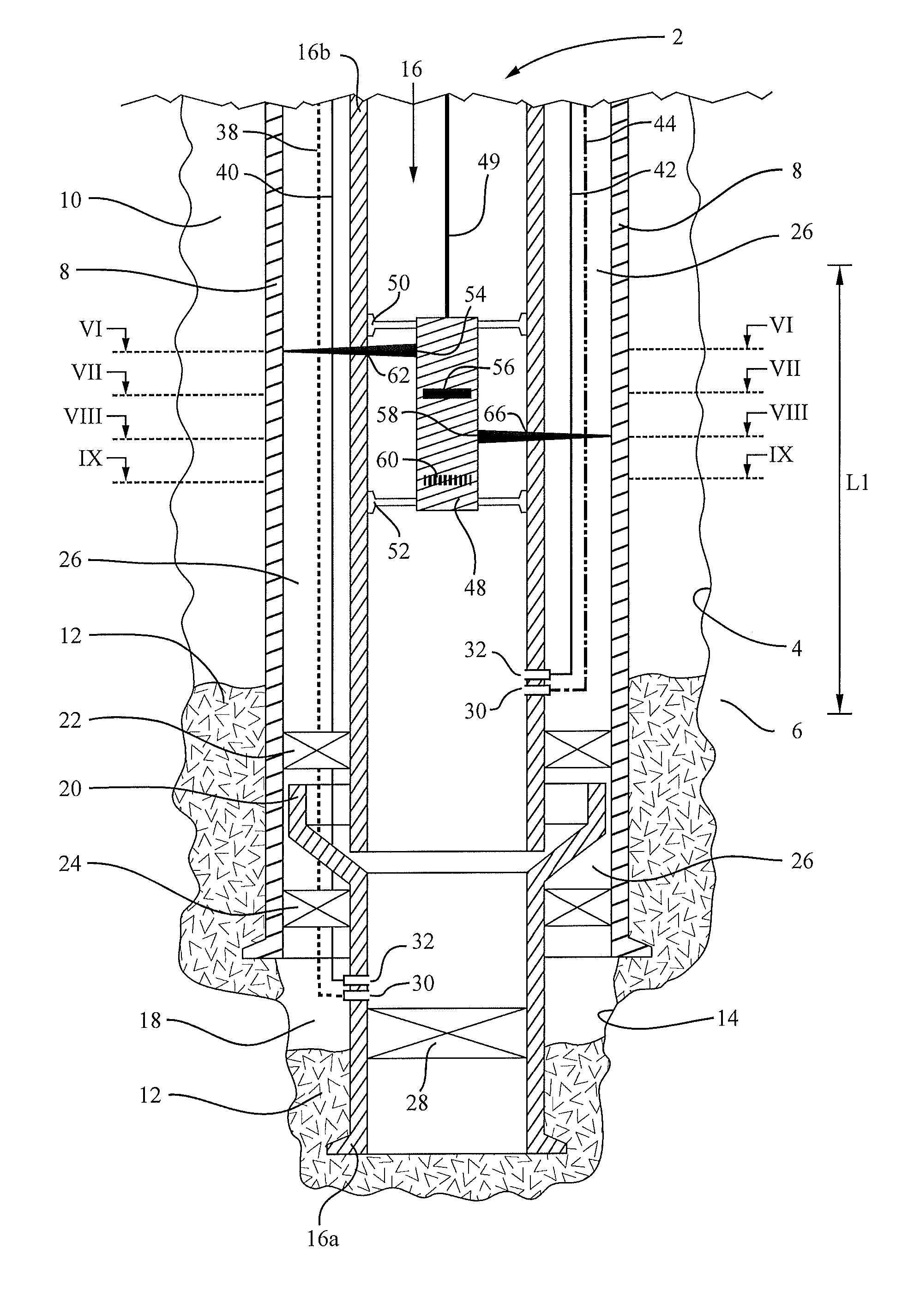
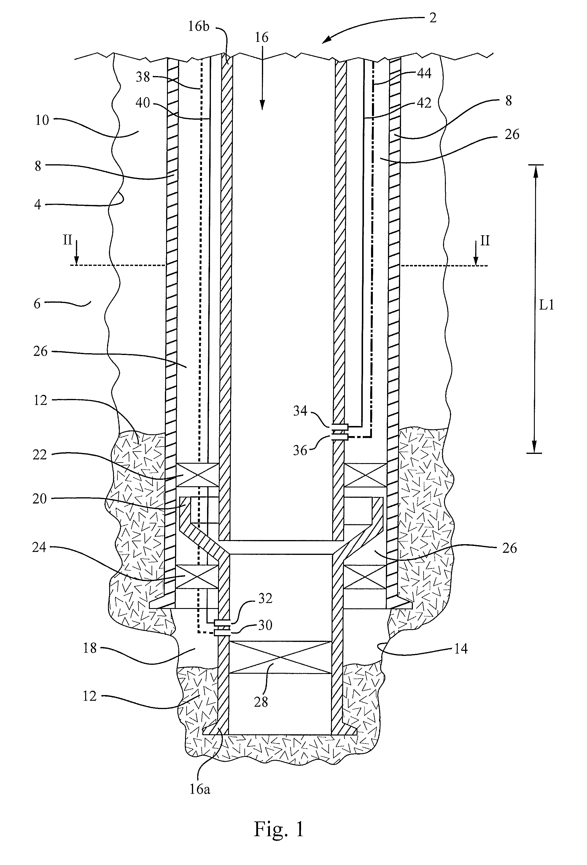
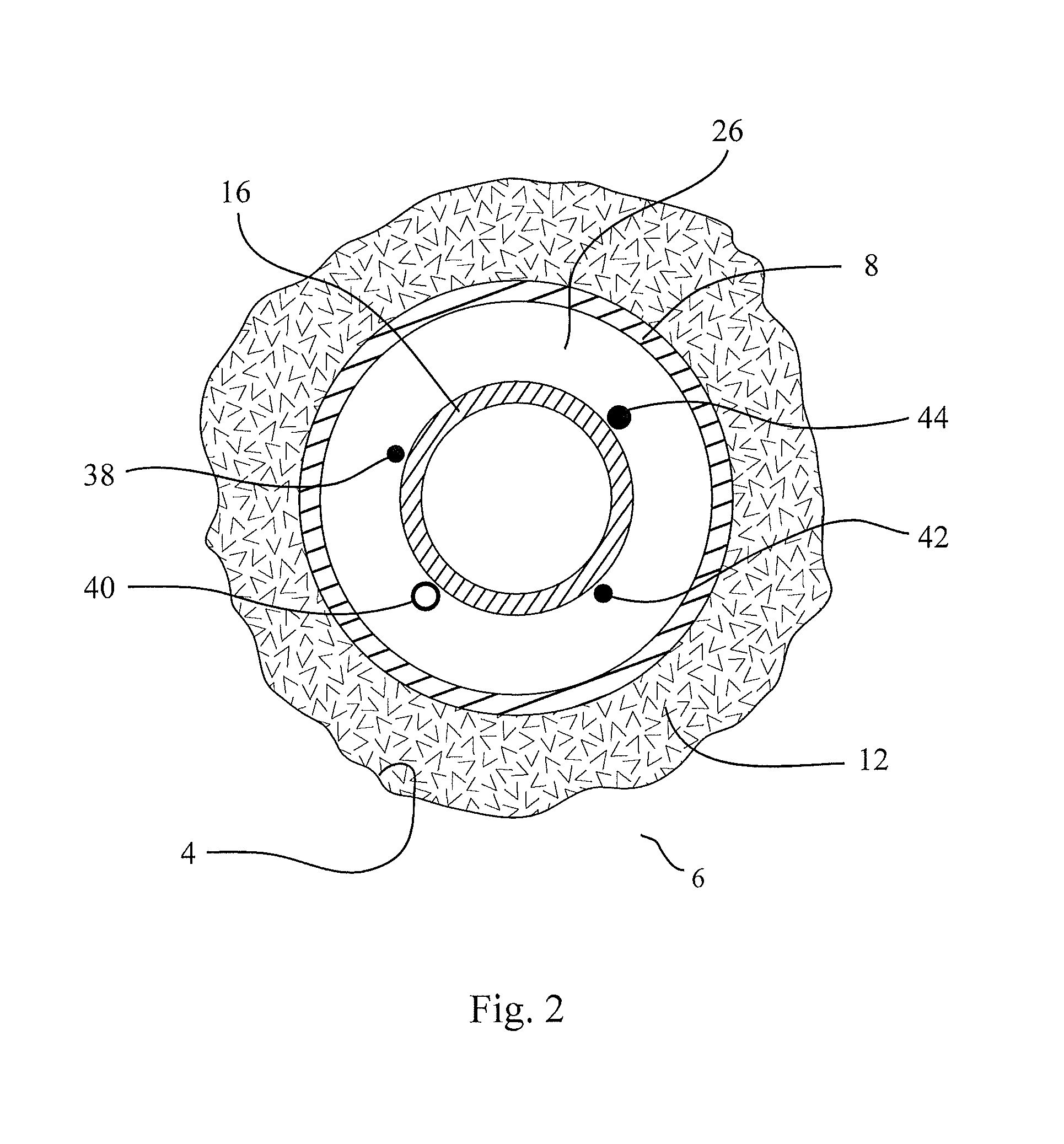
[0101]FIG. 1 shows a portion of a typical petroleum well 2 containing a longitudinal section L1 to be plugged in accordance with prior art. The well 2 has been formed in a known manner by drilling a first borehole 4 through a subterranean formation 6, after which a casing string 8 has been lowered into the borehole 4 to be fixed therein by circulating cement slurry into an annulus 10 located between the formation 6 and the casing string 8. Subsequently, the cement slurry has hardened into cement 12 in the annulus 10.

[0102]A second borehole 14, which has a smaller diameter than the first borehole 4, has then been drilled further down into the subterranean formation 6 and through one or more petroleum reservoirs (not shown), whereupon a production tubing string 16 has been conducted into the casing string 8 and further down into the second borehole 14. The production tubing string 16 has been fixed in the well 2 by circulating cement slurry into an annulus 18 located between the forma...


PUM


Abstract

A method is for cutting of at least one line disposed along a pipe string in a well. The method includes (A), using a cutting tool for selective cutting activation and provided with at least one cut-forming means for cutting in a radial direction outward from the cutting tool; and (B) lowering the cutting tool to a longitudinal section where the cutting is to be carried out. In (A), a cutting tool is used for controlled cutting in a peripheral direction and distributed in an axial direction relative to the cutting tool. The method further includes (C), activating the cutting tool and cutting, in the radial direction through and past the wall of the pipe string, at least one peripherally extending hole collectively covering the entire circumference of the pipe string, and also distributing the hole in the axial direction.

Description

FIELD OF THE INVENTION[0001]The present invention concerns a method for downhole cutting of at least one line disposed outside and along a pipe string in a well, and without simultaneously severing the pipe string. The method is suitable, as an introductory measure, in context of temporary or permanent plugging of one or more longitudinal sections of a well.[0002]The well may be comprised of any type of subterranean well, for example a petroleum well, injection well, exploration well, geothermal well or water well, and the well may be located onshore or offshore.BACKGROUND OF THE INVENTION[0003]Typically, a subterranean well is provided with several sizes of more or less concentric pipe strings extending individually and successively, and with a diminishing tubular cross section, down to increasingly larger depths in the well. Pipes in such pipe strings typically are referred to as casings, liners, production tubings, injection tubings or similar. The primary object of the pipe stri...

Claims


Application Information

Patent Timeline
IPC IPC(8): E21B29/04E21B33/13
CPCE21B33/13E21B29/04
Inventor MYHRE, MORTENLARSEN, ARNE GUNNARJENSEN, ROY INGEANDERSEN, PATRICKENGELSGJERD, ERLENDIUELL, MARKUSOSTVOLD, ARNOLDDAHL, ARNT OLAV
Owner HYDRA SYST
Why Eureka
Try Eureka