

Gas turbine silencer, and gas turbine provided with same
- Summary
- Abstract
- Description
- Claims
- Application Information
AI Technical Summary
Benefits of technology
Problems solved by technology
Method used
Image

Examples
embodiment 1
Schematic Configuration and Overall Operation of Gas Turbine 1
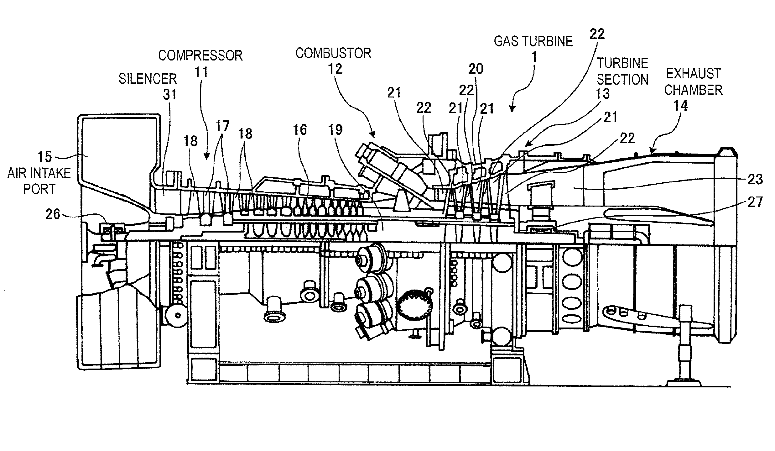
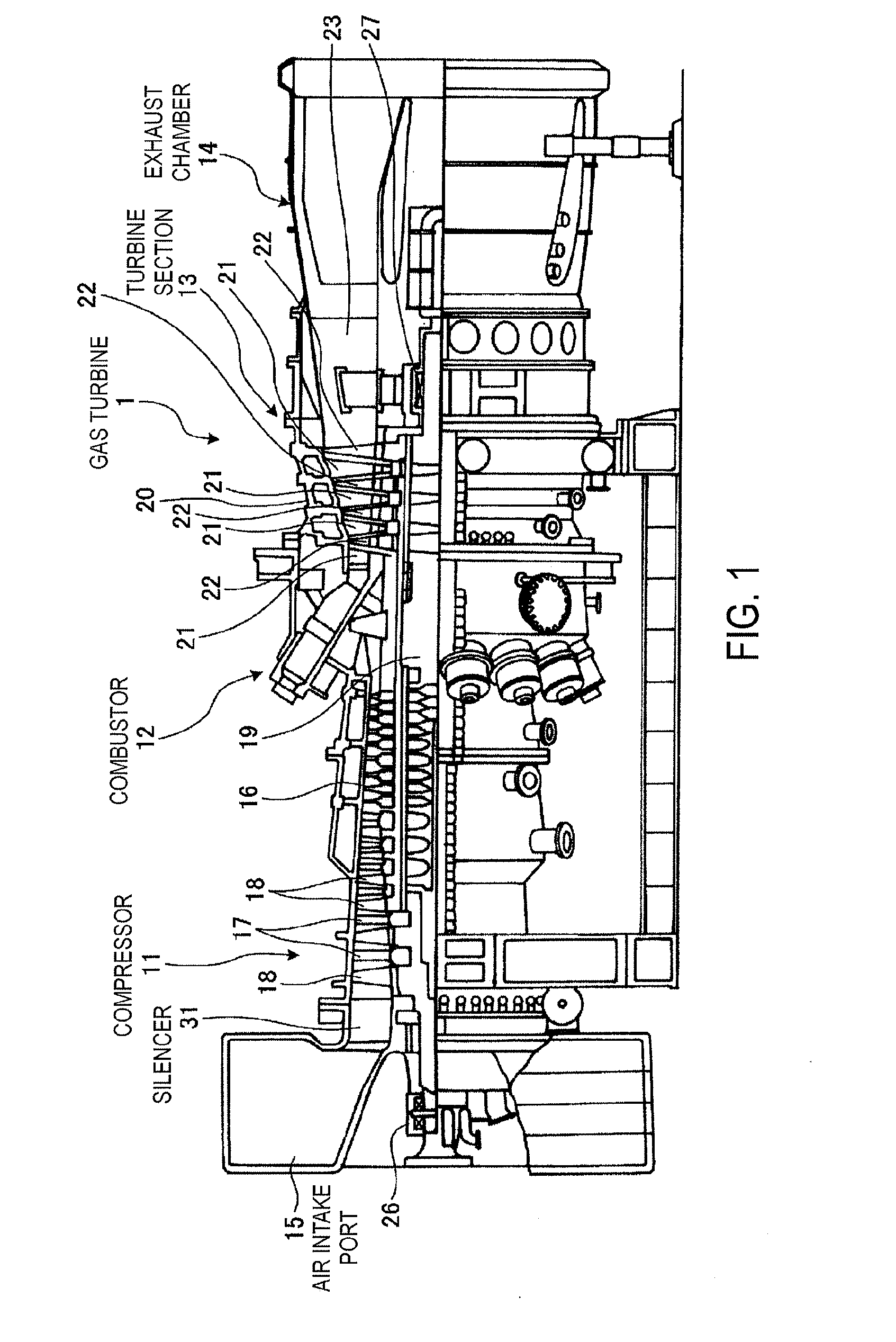
[0041]FIG. 1 is schematic configuration diagram of a gas turbine according to embodiment 1 of the present invention. With reference to FIG. 1, description will be given of the schematic configuration of a gas turbine 1 according to the present embodiment.
[0042]As illustrated in FIG. 1, the gas turbine 1 according to the present embodiment is provided with a compressor 11, a combustor 12, a turbine section 13, and an exhaust chamber 14. In addition, a rotor 19 is arranged so as to pass through a center section of the compressor 11, the combustor 12, the turbine section 13, and the exhaust chamber 14. A driving shaft of a generator (not illustrated) is linked with the end section of the rotor 19 on the exhaust chamber 14 side.
[0043]The compressor 11 is provided with an air intake port 15 for taking in outside air, a plurality of vanes 17 and blades 18 alternately arranged in a compressor casing 16, and a silencer 31 install...
embodiment 2
[0062]Description will be given of the gas turbine silencer according to embodiment 2 of the present invention focusing on the points which are different to the gas turbine silencer according to embodiment 1. Here, the configuration and operation of the gas turbine provided with the gas turbine silencer according to embodiment 2 are the same as that of the gas turbine 1 according to embodiment 1 illustrated in FIG. 1. In addition, the operation of the effect of reducing the noise accompanying the flow of air due to the air passing through the gas turbine silencer according to embodiment 2 is the same as for the gas turbine silencer according to embodiment 1.
Structure of Silencer 31
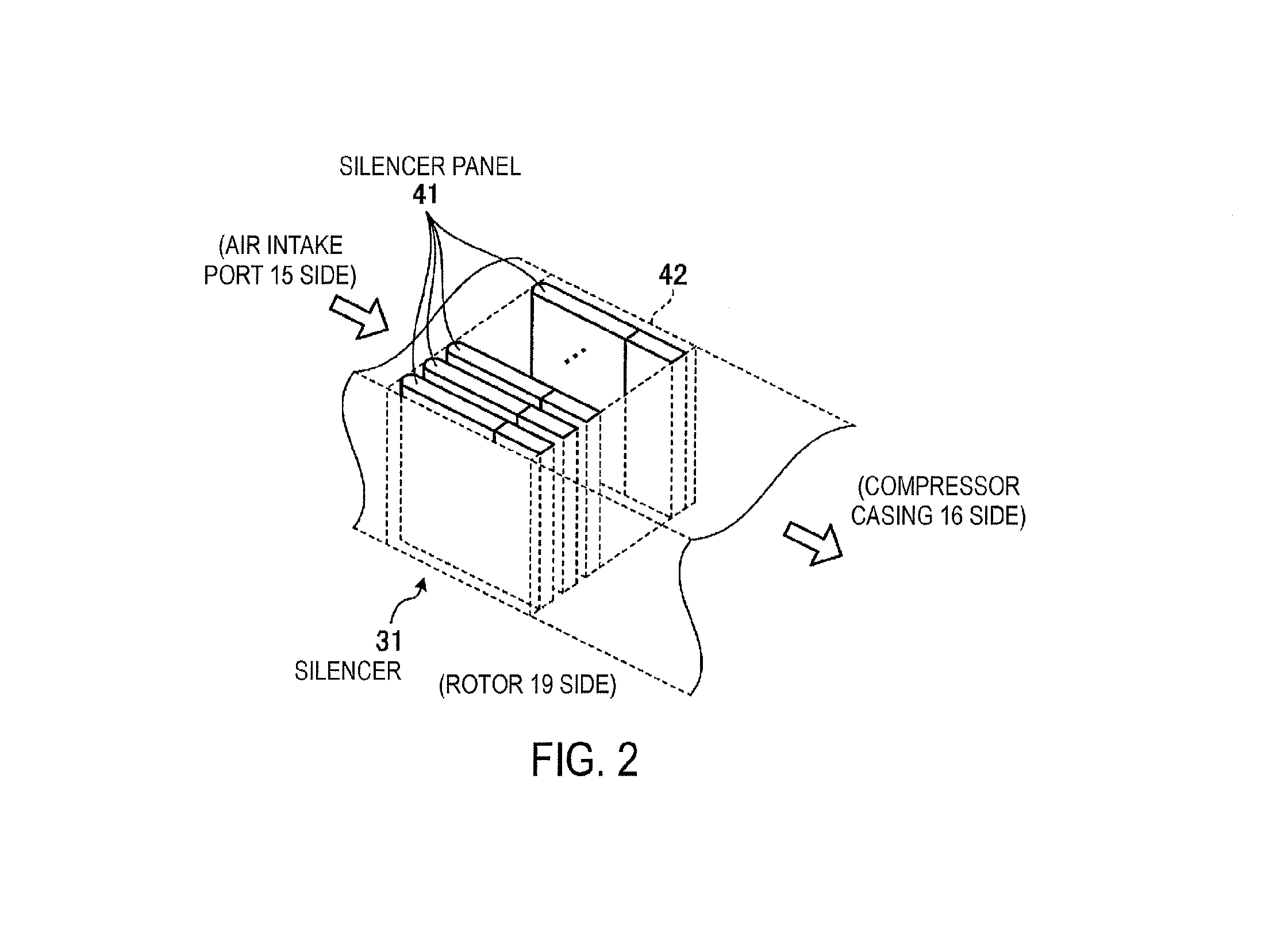
[0063]In the duct 42 between the air intake port 15 and the compressor casing 16, the silencer 31 (refer to FIG. 1) is configured so that a plurality of plate-shaped silencer panels 41a (divided silencer panels) to be described below has the plate surfaces thereof aligned along the airflow direction from t...
embodiment 3
[0069]Description will be given of the gas turbine silencer according to embodiment 3 of the present invention focusing on the points which are different to the gas turbine silencer according to embodiment 1. Here, the configuration and operation of the gas turbine provided with the gas turbine silencer according to embodiment 3 are the same as that of the gas turbine 1 according to embodiment 1 illustrated in FIG. 1. In addition, the operation of the effect of reducing the noise accompanying the flow of air due to the air passing through the gas turbine silencer according to embodiment 3 is the same as for the gas turbine silencer according to embodiment 1.
Structure of Silencer 31
[0070]In the duct 42 between the air intake port 15 and the compressor casing 16, the silencer 31 (refer to FIG. 1) is configured so that a plurality of plate-shaped silencer panels 41b (divided silencer panels) to be described below has the plate surfaces thereof aligned along the airflow direction from t...
PUM
 Abstract
Description
Claims
Application Information